25
SECTION 6 - COMMISSIONING INSTRUCTIONS
6 COMMISSIONING
INSTRUCTIONS
Before commissioning the boiler, the whole gas installation including
the meter (if tted) MUST be purged and tested for gas soundness.
Purge air from the gas installation by the approved methods only.
WARNING. Whilst effecting the required gas soundness test
and purging air from the gas installation, open all windows
and doors, extinguish naked lights and DO NOT smoke.
Ensure that the ue has been installed correctly and no vents are
blocked. Before commencing commissioning, ensure that the CH
system and DHW and cold water system have been ushed. The
CH system needs to be treated with water treatments that are
approved for use with aluminium alloy heat exchangers.
If water is connected to the gas inlet point on the holiday
home and then turned on, DO NOT TURN THE BOILER ON.
Contact Morco Products Ltd. immediately for advice.
6.1 GENERAL
Please Note: The combustion for this appliance has been
checked, adjusted and preset at the factory for operation on
the gas type dened on the appliance data plate. As part of the
commissioning process, the combustion of this appliance must be
checked. A owchart to assist is provided on page 40.
DO NOT adjust the air/gas ratio valve.
Having checked:
- That the boiler has been installed in
accordance with these instructions.
- The integrity of the ue system and
the ue seals, as described in the
Flue Installation section.
Proceed to put the boiler into operation
as follows:
CHECK THE OPERATIONAL
(WORKING) GAS INLET
PRESSURE
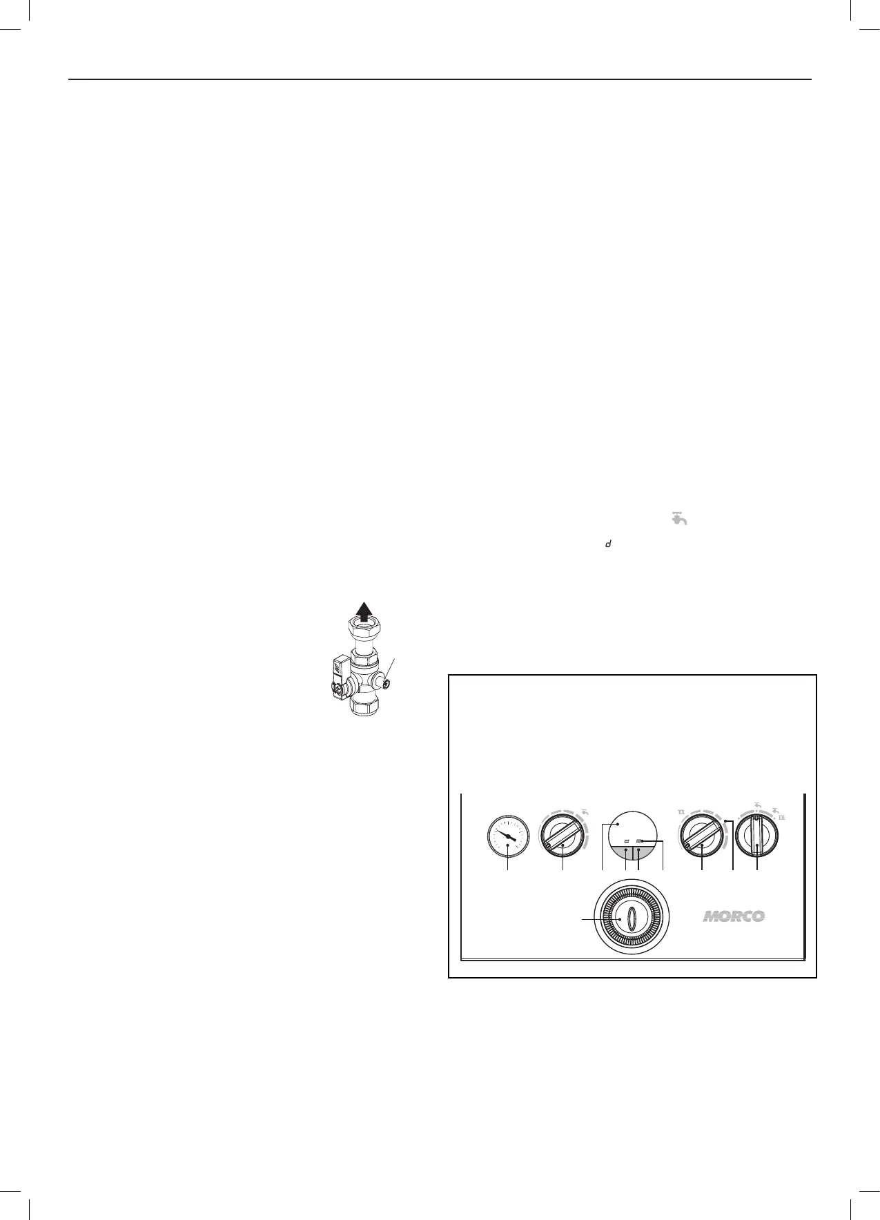
Set up the boiler to operate at maximum rate by opening hot tap
to maximum ow.
With the boiler operating in the maximum rate condition check
that the operational (working) gas pressure at the inlet gas
pressure test point complies with the requirements - refer to “Gas
Supply” on page 15.
Ensure that this inlet pressure can be obtained with all other gas
appliances in the property working at maximum.
6.2 DOMESTIC HOT WATER
Turn on the main cold water supply.
Fill and vent the installation by turning on and off the various hot
water taps in the installation.
Check hot water taps in the installation.
Check for and repair leaks as necessary.
6.3 CENTRAL HEATING CIRCUIT
Fill the siphon in the condense pipework prior to operating.
In order for the boiler to function correctly, the pressure in the
central heating circuit must be between 1 and 1.5 bar on the
pressure gauge.
Both the boiler and central heating installation must be purged of
any air. The boiler has an auto air vent integral to the pump which
must be loose prior to commissioning.
Add an approved ushing solution to one of the radiators.
Fill the central heating circuit using one of the approved methods
to 1 bar.
Open radiator vent screws and turn off when water appears.
Turn off the lling method and disconnect.
With the system hot, examine all water connections. The system
pressure should not exceed 2.5 bar.
Turn off gas, water and electricity when draining down.
Rell and vent the system, add inhibitor and anti-freeze in the
required concentration and check for water leaks.
Check that the condensate operates and the pipework for any
leaks.
6.4 INITIAL OPERATION
Ensure central heating circuit is full and vented, and pressure
gauge is reading 1.0 bar.
6.5 DOMESTIC HOT WATER MODE
Turn the “mode” control knob to tap icon .
Display alternates between “ H” and the current temperature. The
“Burner on” indicator will illuminate when the burner is lit.
Check the DHW functions by turning on a hot water tap.
Close the DHW tap.
Display will read “00”.
Gas
Supply
Gas
Pressure
Test
Point
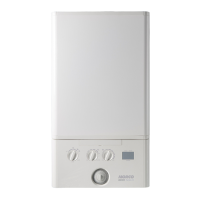
A.
Domestic Hot Water Temperature Knob
B. Central Heating Temperature Knob
C. Mode Knob
D. Boiler Status Display
E. Function Button
F. Burner ‘on’ Indicator
G. Restart Button
H. Central Heating Economy Setting
J. Pressure Gauge
K. Timer
Legend
8 8
restart
min
max
min
max
mode
off
e
restart
IV
A
K
J BFD GE CH


 To Next Page
 Loading...