13
SECTION 3 - TECHNICAL DATA
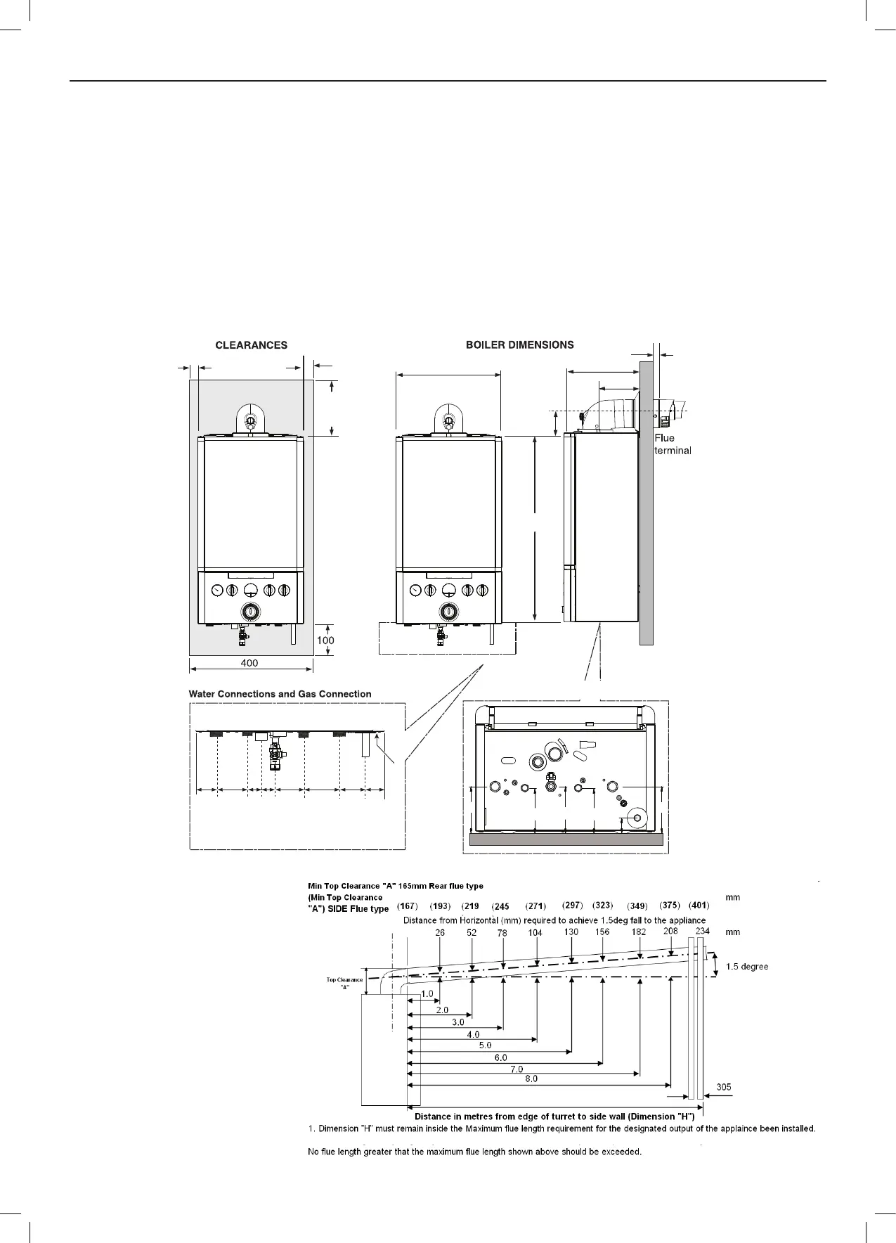
3.2 BOILER DIMENSIONS, SERVICES & CLEARANCES
The following minimum clearances must be maintained for
operation and servicing.
Additional space will be required for installation, depending upon
site conditions.
Side and Rear Flue
a. Provided that the ue hole is cut accurately, e.g. with a core
boring tool or hole cutter the ue can be installed from inside
the dwelling where wall thicknesses do not exceed 600mm.
Where the space into which the boiler is going to be installed
is less than the length of ue required the ue must be tted
from the outside.
Installation from inside ONLY
b. If a core boring tool or hole cutter is to be used inside the
dwelling the space in which the boiler is to be installed must
be at least wide enough to accommodate the tool.
In either of the above cases safe external access is required
to allow the addition of sealant to seal around the ue to the
aluminium ue collar (RSF 060).
Front clearance
The minimum front clearance when
built in to a cupboard is 5mm from
the cupboard door but 450mm overall
clearance is still required, with the
cupboard door open, to allow for
servicing.
Bottom clearance
Bottom clearance after installation
can be reduced to 5mm.
This must be obtained with an easily
removable panel, to enable the
consumer to provide the 100mm
clearance required for servicing.
Max 30kW
Max 24kW
2. For ue lengths requiring extensions (RSF 341), the ue must incline by 26mm per 1 Metre of ue length.
DATA PLATE
CH FLOW
DHW OUTLET
COND. DRAIN
GAS INLET
DHW INLET
CH RETURN
PRV
W A L L
Underside View - Dimensions to Wall
3952.5
2.5
from case
700
Side
flue
dim. A
285
86.5
17
155
43.5 65
28.5 28.5
60.5 75 39.554.5
WALL
103
34
9910399
103
 Loading...