23
SECTION 5 - INSTALLATION INSTRUCTIONS
2. Ensure that if the length needs to be adjusted to allow an additional 30mm added to
the outer air tube length 14mm added to the inner ue length. This allows correct
engagement into the vertical connector.
Note. Ensure a square cut. Remove all burrs and sharp edges.
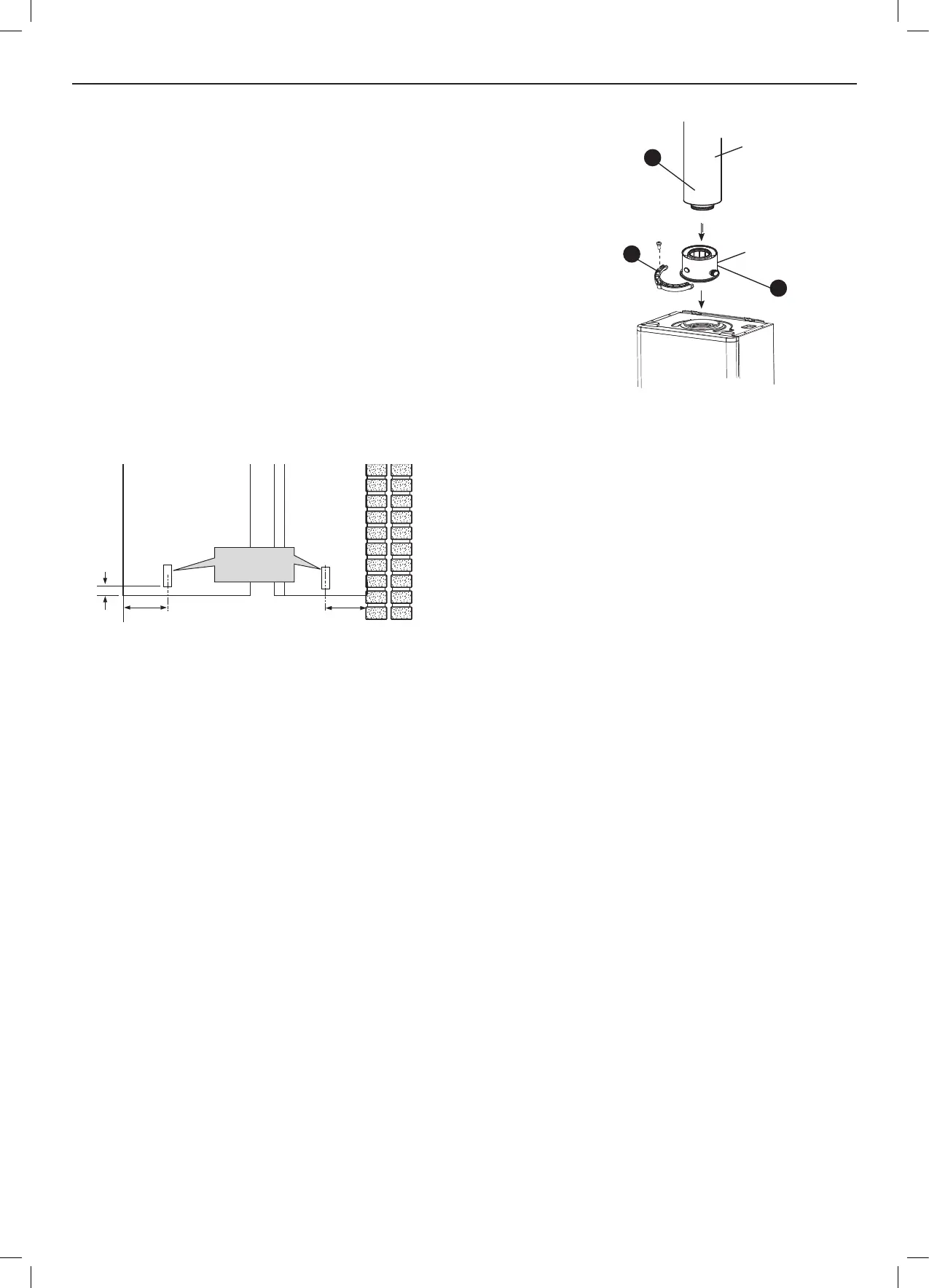
3. Fit the vertical connector (supplied in the kit) and secure the vertical connector by
applying downward pressure on the connector.
4. Position the clamp on the top face of the ue manifold and push it horizontally
backwards. Locate both clamp lugs into the ue manifold and secure to the ue
manifold clamp with the M5 retaining screw.
5. “Push” assembly A into vertical connector.
Notes. Ensureturretsamplepointsareserviceableandallcapsandplugsaretted.
Ensurecondensatesiphon/trapislledwithwater.
6. Finally ensure the roof plate is correctly sealed to the roof.
Assembly A
5
3
Vertical
connector
4
5.19 CONDENSATE DRAIN
137
47
156
Condensate
Drain
This appliance is tted with a siphonic 75mm sealed condensate
trap system that requires lling before operating the appliance for
the 1st time or after maintenance.
All condensate pipework should conform to the following:
a. Where a new or replacement boiler is being installed, access to
an internal ‘gravity discharge’ termination should be one of the
main factors considered in determining boiler location.
b. Plastic with push t or solvent connections.
c. Internal plastic pipe work a minimum of 19mm ID (typically
22mm OD)
d. External plastic pipe must be a minimum of 30mm ID (typically
32 OD) before it passes through the sleeved wall.
e. All horizontal pipe runs, must fall a minimum of 45mm per metre
away from the Boiler.
f. External & unheated pipe work should be kept to a minimum
and insulated with Class “O” waterproof pipe insulation.
g. All installations must be carried out in accordance to the
relevant connection methods as shown in the “Condensate
installation diagrams” & BS 6798:2014
h. Pipe work must be installed so that it does not allow spillage
into the dwelling in the event of a blockage (through freezing)
i. All internal burrs should be removed from the pipe work and any
ttings.
Note. Clip runs to prevent pipework disconnecting due to
vibration etc.
In order to minimise the risk of freezing during prolonged very cold
spells, one of the following methods of terminating condensate
drainage pipe should be adopted.
Internal Drain Connections
Wherever possible, the condensate drainage pipe should be routed
to drain by gravity to a suitable internal foul water discharge point
such as an internal soil and vent stack or kitchen or bathroom
waste pipe etc. See Figs 1 and 2.
Condensate Pump
Where gravity discharge to an internal termination is not physically
possible or where very long internal pipe runs would be required
to reach a suitable discharge point, a condensate pump of a
specication recommended by the boiler or pump manufacturer
should be used terminating into a suitable internal foul water
discharge point such as an internal soil and vent stack or internal
kitchen or bathroom waste pipe etc. (g 3).
External Drain Connections
The use of an externally run condensate drainage pipe should
only be considered after exhausting all internal termination options
as described previously. An external system must terminate at a
suitable foul water discharge point or purpose designed soak away.
If an external system is chosen then the following measures must
be adopted:
The external pipe run should be kept to a minimum using the most
direct and “most vertical” route possible to the discharge point, with
no horizontal sections in which condensate might collect.
- For connections to an external soil/vent stack see Fig 4.
Insulation measures as described should be used.
- When a rainwater downpipe is used, an air break must be
installed between the condensate drainage pipe and the
downpipe to avoid reverse ow of rainwater into the boiler
should the downpipe become ooded or frozen, see Fig 5.
- Where the condensate drain pipe terminates in a purpose
designed soakaway (see BS 6798:2014) any above ground
condensate drain pipe sections should be run and insulated as
described above. See Fig 6.
- Where the condensate drain pipe terminates over an open
foul drain or gully, the pipe should terminate below the grating
level, but above water level, to minimise “wind chill” at the open
end. The use of a drain cover (as used to prevent blockage by
leaves) may offer further prevention from wind chill.
Unheated Internal Areas
Internal condensate drain pipes run in unheated areas should be
treated as external pipe.
Ensure the customer is aware of the effects created by a frozen
condensate and is shown where this information can be found in
the user manual.
continued . . . . .
ASSEMBING THE ROOF FLUE KIT - CONT’D
 Loading...