8
SECTION 1 - USERS INSTRUCTIONS
1.14 LOSS OF SYSTEM WATER PRESSURE
The pressure gauge indicates the central
heating system pressure. If the pressure is
seen to fall below the original installation
pressure of 1-2 bar over a period of time then
a water leak may be indicated. In this event
re-pressurise the boiler. If unable to do so or
if the pressure continues to drop a Gas Safe
Registered Engineer, or in other countries a
qualied and competent Gas Installer should
be consulted.
INDICATED BY “F1” (LOW WATER PRESSURE) - THE BOILER
WILL NOT OPERATE IF THE PRESSURE HAS REDUCED TO
LESS THAN 0.3 BAR UNDER THIS CONDITION.
1.15 CONDENSATE DRAIN
This appliance is tted with a siphonic condensate trap system
that reduces the risk of the appliance condensate from freezing.
However should the condensate pipe to this appliance freeze,
please follow these instructions:
a. If you do not feel competent to carry out the defrosting
instructions below please call your local Gas Safe Registered
Engineer, or in other countries a qualied and competent Gas
Installer for assistance.
b.
If you do feel competent to carry out the following instructions
please do so with care when handling hot utensils. Do not attempt
to thaw pipework above ground level.
If this appliance develops a blockage in its condensate pipe, its
condensate will build up to a point where it will make a gurgling
noise prior to locking out an “L2” fault code. If the appliance is
restarted it will make a gurgling noise prior to it locking out on a
failed ignition “L2” code.
To unblock a frozen condensate pipe;
1. Follow the routing of the plastic pipe from its exit point on the
appliance, through its route to its termination point.
Locate the frozen blockage. It is likely that the pipe is frozen
at the most exposed point external to the building or where
there is some obstruction to ow. This could be at the open
end of the pipe, at a bend or elbow, or where there is a dip in
the pipe in which condensate can collect. The location of the
blockage should be identied as closely as possible before
taking further action.
2. Apply a hot water bottle, microwaveable heat pack or a warm
damp cloth to the frozen blockage area. Several applications
may have to be made before it fully defrosts. Warm water can
also be poured onto the pipe from a watering can or similar.
DO NOT use boiling water.
3. Caution when using warm water as this may freeze and cause
other localised hazards.
4.
Once the blockage is removed and the condensate can ow
freely, restart the appliance. (Refer to “To Operate the boiler”)
5.
If the appliance fails to ignite, call your Gas Safe Registered Engineer,
or in other countries a qualied and competent Gas Installer.
Preventative solutions:
During cold weather, set the ‘radiator symbol’ to maximum. (Must
return to original setting once cold spell is over.)
Place the heating on continuous and turn the room stat down to 15ºC
overnight. (Return to normal after cold spell.)
1.16 ESCAPE OF GAS
Should a gas leak or fault be suspected contact the Gas Supplier
without delay. TURN OFF ALL GAS SUPPLIES.
Do NOT search for gas leaks with a naked ame.
1.17 CLEANING
For normal cleaning simply dust with a dry cloth.
To remove stubborn marks and stains, wipe with a damp cloth
and nish off with a dry cloth.
DO NOT use abrasive cleaning materials.
1.18 MAINTENANCE
The appliance should be serviced at least once a year by a Gas Safe
Registered Engineer, or in other countries a qualied and competent
Gas Installer.
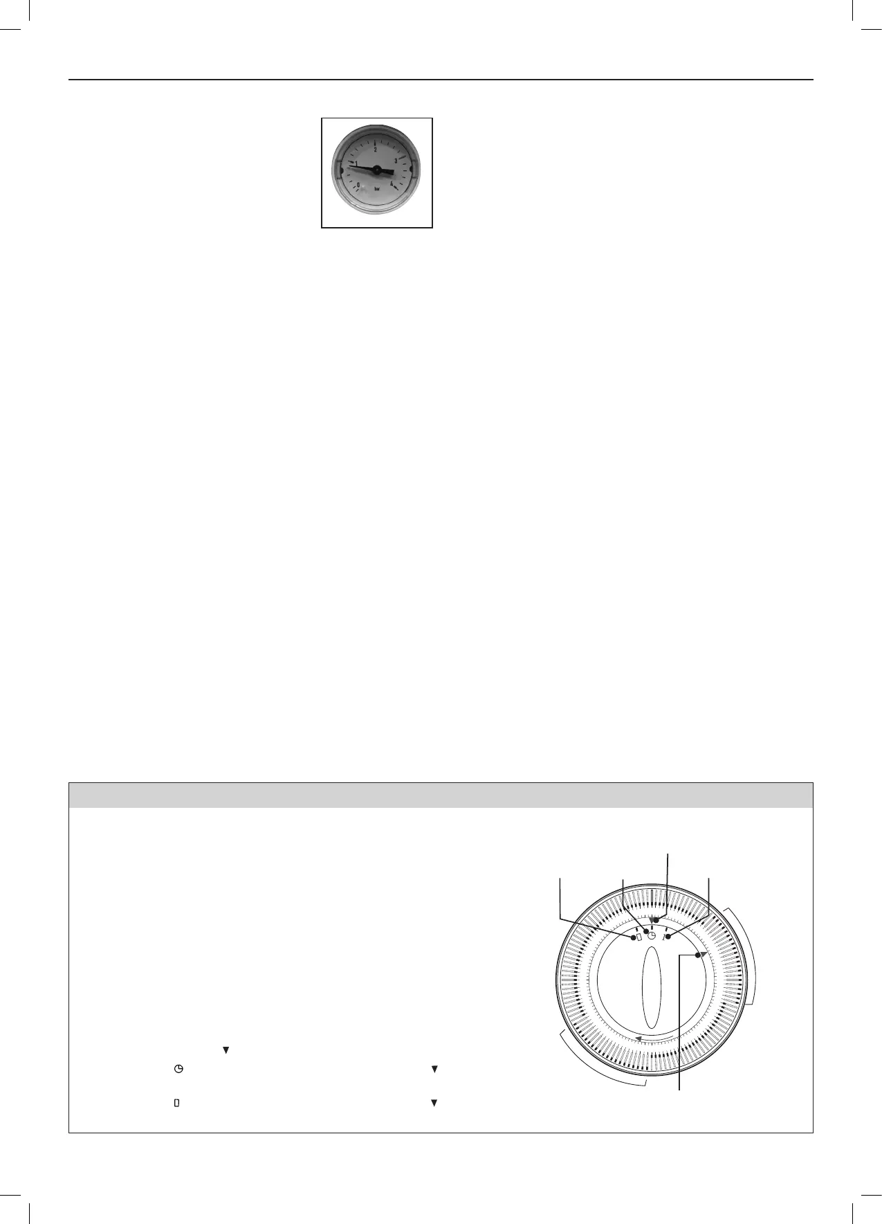
1.19 MECHANICAL 24 HOUR TIMER
PROGRAMMING THE TIMER
1.
Decide what times you would like the timeswitch to switch ON and OFF.
2. Push segments towards the programme ring for an OFF period and
push away from ring for an ON period. The minimum switching
interval is 15 minutes and this can be increased in 15 minute steps.
3. Bring the timeswitch into the correct condition by manually turning
the programme ring clockwise through a 24 hour cycle.
4. Turn the programme ring clockwise until the correct time of day on
the ring lines up with the time indicator.
Note. The segment dial can be turned when the time controller is
operating. In case of power failure, re-adjust the time controller to the
correct time of day, turning the dial in a clockwise direction.
Permanent Override
By rotating the central switch so that the symbol (1) lines up with the
operating mode indicator ( ) the unit will be permanently ON.
With the symbol ( ) lining up with the operating mode indicator ( ) the
unit acts as a timeswitch.
With the symbol ( ) lining up with the operating mode indicator ( ) the
unit will be permanently OFF.
Permanently o Permanently on
Time Indicator
Align current time to arrow
Timer Control
Operating Mode Indicator
1
2
3
4
5
6
7
8
9
10
11
12
13
14
15
16
17
18
19
20
21
22
23
24
O
N
P
e
r
i
o
d
O
N
P
e
r
i
o
d

 Loading...