Universal Calibrang Machine
(UCM) Manual
(PM-5201)
Morehouse Instrument Company, Inc.
1742 Sixth Ave., York, PA 17403-2675 USA
Phone: (717) 843-0081
www.mhforce.com
Page 28
Rev. 3/2024
Check for clearance between the tension member and the underside of the lower machine platen. This clear-
ance should be approximately 1/8 inch. If it is greater than 1/8 inch, raise the lower yoke platen as needed.
Always check to be sure there is clearance between the unit under test and its adapters and the lower machine
platen.
Cauon: Always be sure any fasteners supplied or used with tension members are fully engaged.
4.4 Hand Pump Operaon
The hand pump supplied with the calibrang machine is a dual-volume design based on a double-diameter
piston. On the side of the pump is a valve rod (Figure 5) with a round handle. With the rod pulled out, the full
diameter of the piston is eecve for large-volume, low-pressure pumping; with the rod pushed in, the re-
duced diameter is eecve for high-pressure with a minimum pumping eort. To use the Hand Pump, refer to
the operang instrucons supplied with it (Hydraulic Hand Pump & Jack Instrucon Manual).
Cauon: Before pushing in the rod, release any downward pressure applied to the hand lever.
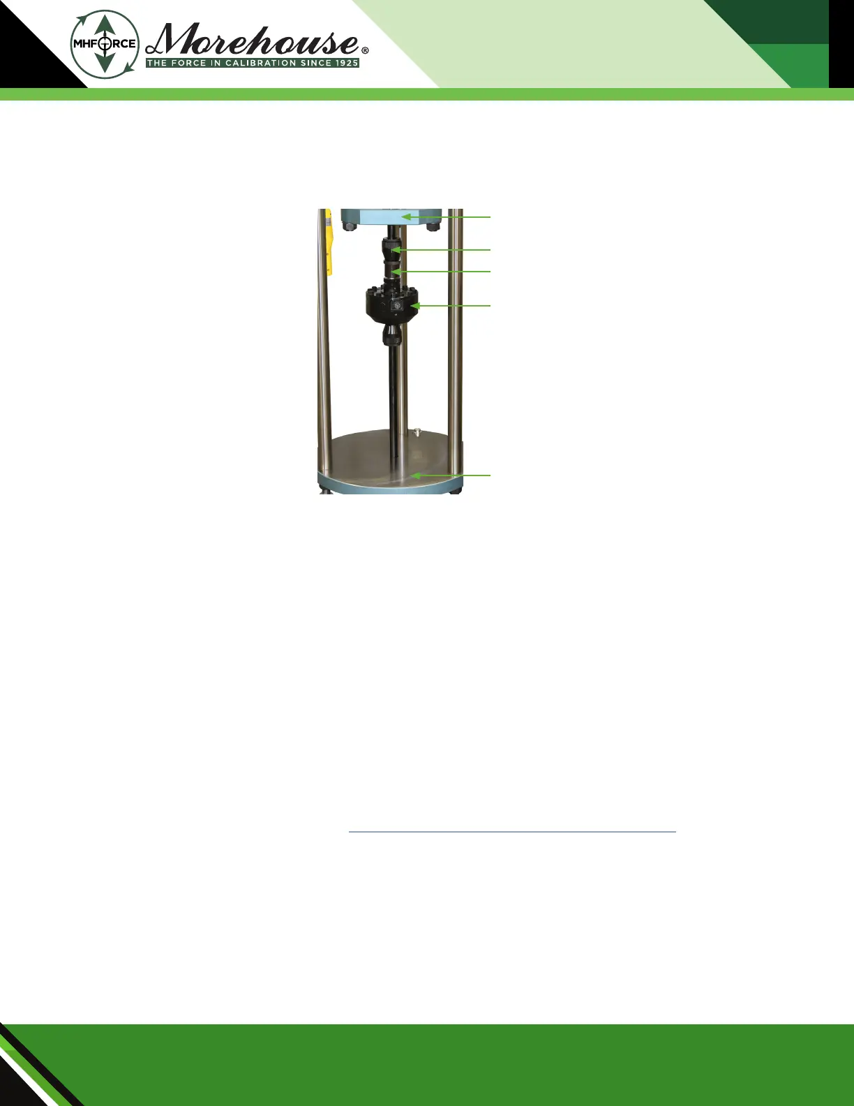
Figure 24: Tension Member Setup
Figure 24 shows the method of connecng a tension member (B) between the unit under test (C) and the low-
er yoke platen (A). The unit under test is connected to the lower machine platen in a similar fashion.
A) Lower Yoke Platen
B) Tension Member
C) Tension Member Adapter
D) Unit Under Test
E) Lower Platen