27
CONFIGURATION 4
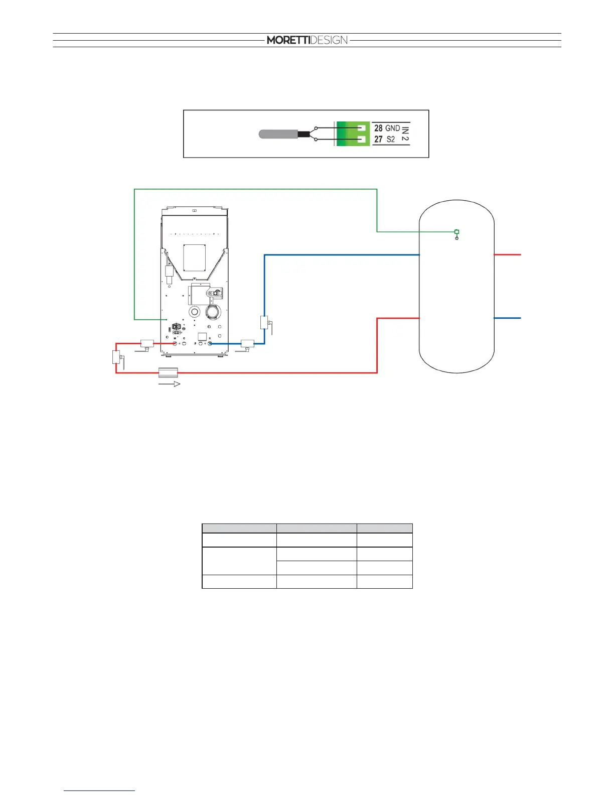
The configuration shown in the figure is set.
Connections on the control unit
Connections on the heating system (the following schematic is only illustrative)
The system includes: the hydro stove Boiler Probe (S1), the hydro stove Pump (P1), Boiler/Puffer Probe (S2).
Set parameters on the hydro stove
T19 = 53°C, T21 = 80°C, T37 = 5°C
Puffer
•
If the temperature in the hydro stove is greater than the pump activating thermostat T19, the system heats the water in the Puffer if there is a difference
between the two probe readings (the hydro stove (S1) temperature minus the Puffer (S2) temperature is greater than the differential thermostat T37).
• For safety reasons, if the water temperature in the hydro stove exceeds the thermostat T21, the Pump (P1) is activated.
System function:
CONFIGURATION 5, 6
THESE CONFIGURATIONS ARE NOT COMPATIBLE WITH HYDRO STOVES PRODUCED BY MORETTI FIRE.
TEMP. PROBE (S1) DIFFERENTIAL PUMP (P1)
T < 53°C
OFF
> 5°C ON
< 5°C
OFF
T > 80°C
ON
T > 53°C
Probe (S2)
Puffer/Boiler
S1
P1
S2
Puffer
sphere
valve
non return
valve
sphere
valve
sphere
valve
sphere
valve