Quick Start Guide
14
Specifications:
© 2021 Morningstar Corporation. All Rights Reserved. MS-003471 v2
In the Box:
#10
Mounting
Screws (x4)
Tools Required:
— #2 Philips Screwdriver
— 3/16 (5 mm) & 1/8" (3.8 mm) Flathead Screwdriver
— Drill with a 1/8" (3.8 mm) bit
— Multimeter
WARNING: Hazardous Voltage
The TriStar charge controller must be installed by
a qualified technician in accordance with the
electrical regulations of the country of installation.
WARNING: Hazardous Voltage
This unit is not provided with a GFDI device. This
charge controller must be used with an external
GFDI device as required by the Article 690 of the
National Electrical Code for the installation
location.
Scan QR Code to go
directly to the TriStar
PWM Installation
Manual and warranty
information online.
Contact Information:
Technical Support: morningstarcorp.com/support
Phone: 1-215-321-4457
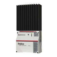
TriStar Solar Charge
Controller
Warranty Registration: https://www.morningstarcorp.com/product-registration/
SOLAR CHARGING SYSTEM CONTROLLER
TS-45 TS-60 TS-60M
TriStar PWM Models:
Optional Accessories
Remote Temperature
Sensor (RTS)
TS-M-2
TS-RM-2
Ethernet MeterBus
Converter (EMC-1)
Mounting
Template
TriStar Charge
Controller
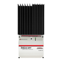
TriStar Charge Controller
(with Optional Meter)
For use with 12 Vdc, 24 Vdc,
or 48 Vdc Systems
Wire Sizes and Torque Requirements:
• Circuit Breakers or fuses are required in the positive cable for Battery, Solar, DC Load, or Diversion Load connections.
• Solar connections require a PV Ground Fault Disconnect.
• A fuse is required in the positive cable for the Voltage Sense connections.
• Fuse or breaker sizing must be based on required wire ampacity.
• If using a fuse, do NOT insert the fuse in the fuse-holder until after all the other connections have been completed.
Fuses and Circuit Breakers:
IMPORTANT:
The TriStar Controller is designed to operate as a solar
charge controller, a load or lighting controller, OR a
diversion controller — one mode at a time and no
combined-mode operation.
Accessing the
wiring terminals:
To Access the Wiring Terminals:
1. Remove the 4 screws and star
washers from the faceplate.
2. Lift the faceplate away from
the base.
To Replace the Faceplate:
1. Align it with the base.
2. Replace the 4 screws and locking washers.
3. Hand tighten, careful not to over-tighten.
1
2
3
4
IMPORTANT:
Refer to Section 2.0, Installation, in the TriStar-PWM manual, for all details on installation requirements.
System design must comply with any applicable electrical code and regulations.
Relay Driver (RD-1)
MeterHub
MeterBus Communication
Hub (HUB-1)
TriStar-PWM-45
TriStar-PWM-60/M
Rated for 75°C Rated for 90°C
#8 AWG (10 mm
2
)#6 AWG (16 mm
2
)
Battery or Load Terminals
Torque
Maximum Length
Ground Terminal
#10 AWG (5 mm
2
)
#8 AWG (8 mm
2
)
MINIMUM WIRE SIZES AND TORQUE REQUIREMENTS
50 in-lbs. (5.56 Nm)
See Table 2.3-6a in the TriStar PWM Installation Manual for Maximum 1-way Wire Distance.
#6 AWG (16 mm
2
)#4 AWG (25 mm
2
)
2
See the Morningstar PV String Calculator at:
https://www.morningstarcorp.com/support/
CAUTION: This guide must be used with the full product manual that includes important information. Carefully
read the TriStar-PWM product manual for all specifications, safety, regulatory and warranty information, and for all
required instructions on installation procedures, configuration, and operation.
TS-45
Battery Voltage 12 Vdc, 24 Vdc, or 48 Vdc
Maximum Solar Input
Voltage
2
12 V Nominal Array Voc
24 V Nominal Array Voc
48 V Nominal Array Voc
Maximum Current
(Solar or Load)
45 A
TS-60
60 A
TS-60M
Battery Operating Voltage 9-68 V
Battery Types Supported Flooded, Sealed
Maximum Current
(Diversion)
30 A 40 A