Fig. 05
Fig. 06
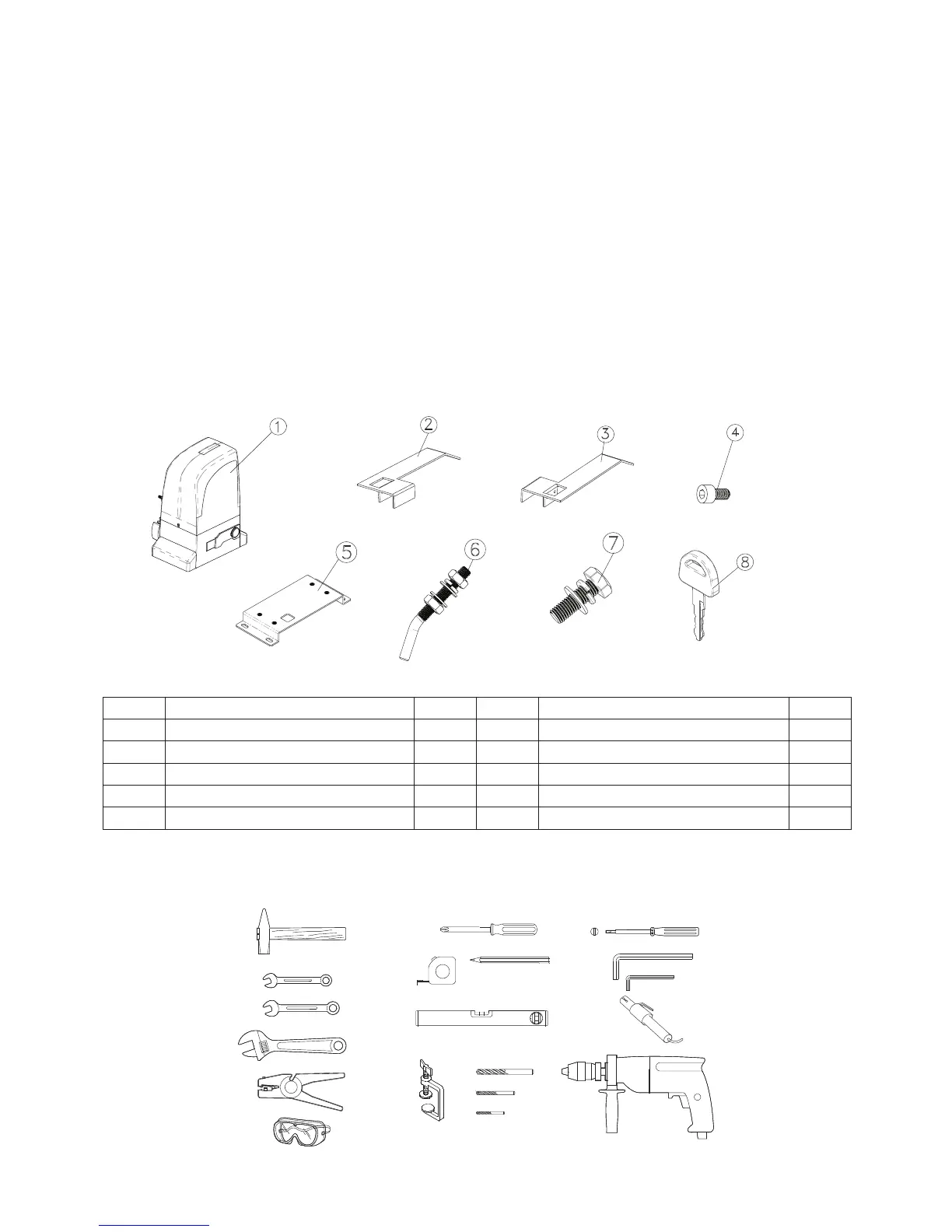
Motor
Left limit switch plate
Right limit switch plate
Screw DIN912 M5x10
Foundation plate
Name
1
1
1
4
1
Qtd
1
2
3
4
5
Nº
6
7
8
9
Nº
Ground Fixation screw
Motor Fixation screw
Key
User Manual
Name
4
4
2
1
Qtd
Note:
1) To lay down electric cables, use rigid and/or exible adequate tubes.
2) To avoid any kind of interference, always separate low voltage connection cables from AC230V power
cables.
3) The description of system is standard system, but we did not provide all parts.
If you want system accessories, please contact us.
You must check the operator packing before installing the automated system.
5) ACCESSORIES
6) INSTALLATION TOOLS
Pág. 04