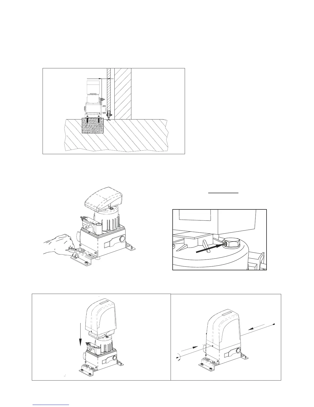
Fig. 13
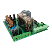
Fig. 15 Fig. 16
7.5. Adjusting the operator
Adjust the distance of the operator from the gate by referring to Fig.13.
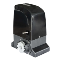
7.6. Fixing operator
Fix the operator slightly tightening the screws as shown in Fig. 14.
After xing the motor, screw cover (Fig. 15 and 16).
57 mm
Pág. 07
Fig. 14
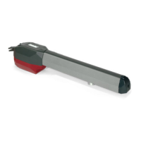
IMPORTANT:
After the installation, you must remove the
exhaust screw (Applicable in OL1500 and 2000)