Basic Theory of Operation: Analog Mode of Operation 3-5
3.2.1.4 700/800 MHz Front-End
From the 15 dB Step Attenuator, a 700/800 MHz band signal is routed to the first band SPST switch
which selects the 700 or the 800 band signal and routes it to the appropriate first pre-selector filter. A
second band select switch selects the output of the appropriate filter and applies it to an LNA
followed by a similar pre-selector filter/ band-select switch circuit. The signal is then routed to a
second LNA whose output is applied to a discrete image filter. Both preselector filters are Surface
Acoustic Wave designs used to band limit the received energy and suppress known spurious
responses such as Image and the ½ IF spur. The output of the discrete image filter is applied to the
RF port of the Mixer IC. The Mixer IC is also excited by a Local Oscillator (LO) signal at the LO port
to down-convert the RF signal to a 109.65 MHz intermediate frequency (IF). The down converted IF
signal is passed through a crystal filter which drives the input of the Abacus 3 Analog to Digital
Converter IC (AD9864).
3.2.1.5 Analog To Digital Converter
The ADC IC's front end down converts the first IF to a second IF, a 2.25 MHz signal. The second IF
is sampled at 18 MHz, a signal generated by an integrated clock synthesizer. The sampled signal is
decimated by a factor of 900 to 20 kHz and converted to SSI format at the ADC's output. The Serial
Synchronous Interface (SSI) serial data waveform is composed of a 16 bit in-phase word (I) followed
by a 16 bit Quadrature word (Q). A 20 kHz Frame Synch and a 1.2 MHz clock waveform are used to
synchronize the SSI IQ data transfer to the Digital Signal Processor IC (OMAP) for post-processing
and demodulation.
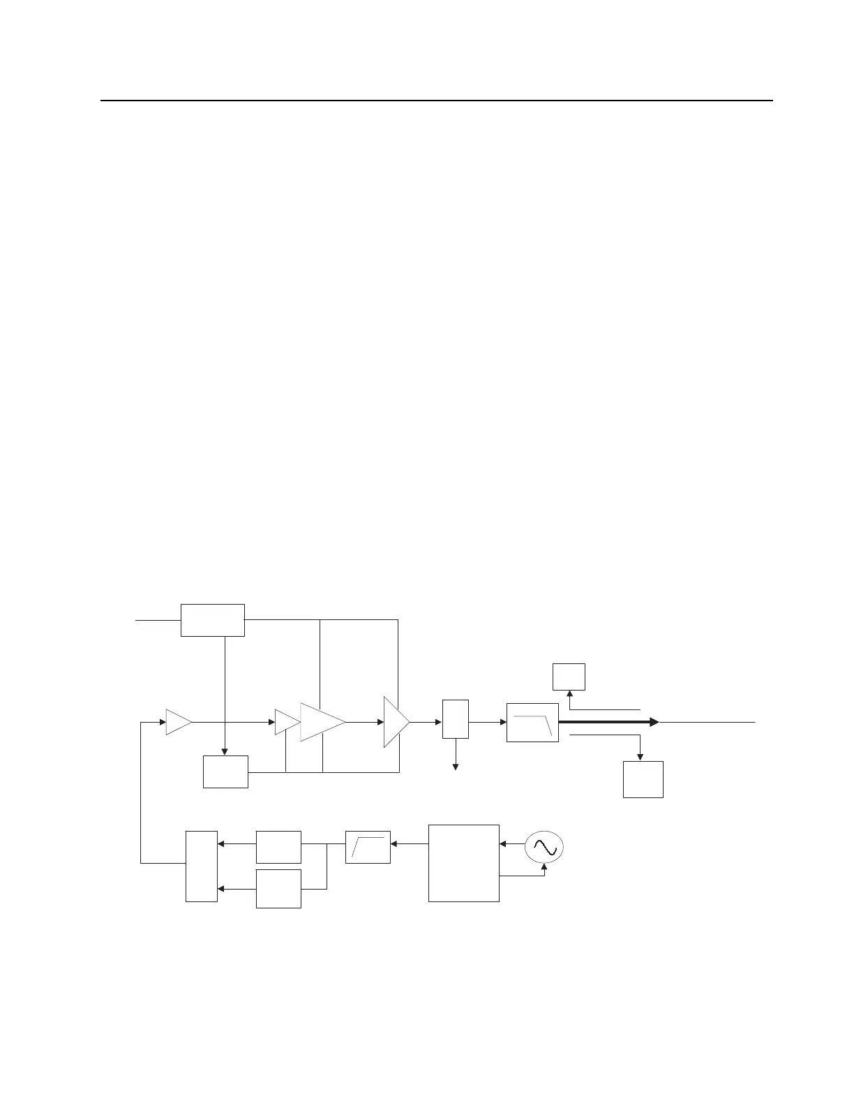
3.2.2 Transmitting
When the radio is transmitting, microphone audio is digitized and then processed by the DSP and
sent to the Trident IC (see Figure 3-6) via the SSI interface. The Trident IC processes the SSI data
for application to the voltage controlled oscillator as a modulation signal.
Figure 3-6. Transmitter Block Diagram
Trident IC
Synthesizer
Loop Filter
TX VCO
RX/TX
VCO
RF Switch Matrix
TX
Buffer Amp
TX Driver
Amplifier
Harmonic
Filter
Ref. Oscillator
To Antenna
Directional
Coupler
Antenna
Switch
TO RX
RX
PDADI
Current
Detection
DC_RAW_B+
ALC
PA
50
Ohm

 Loading...