Disassembly/Reassembly Procedures: Radio Reassembly 8-29
8.6.4 Reassemble the Keypad Board (35)
1. Complete steps in Section 8.6.1. through Section 8.6.3.
2. With the Keypad (37) assembled, place the Keypad Board (35) into the Front Housing (19).
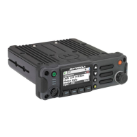
3. Plug in the connector of the Front Kit Flex (3) as shown in Figure 8-39.
Figure 8-38. Plug in the Front Kit Flex Connector
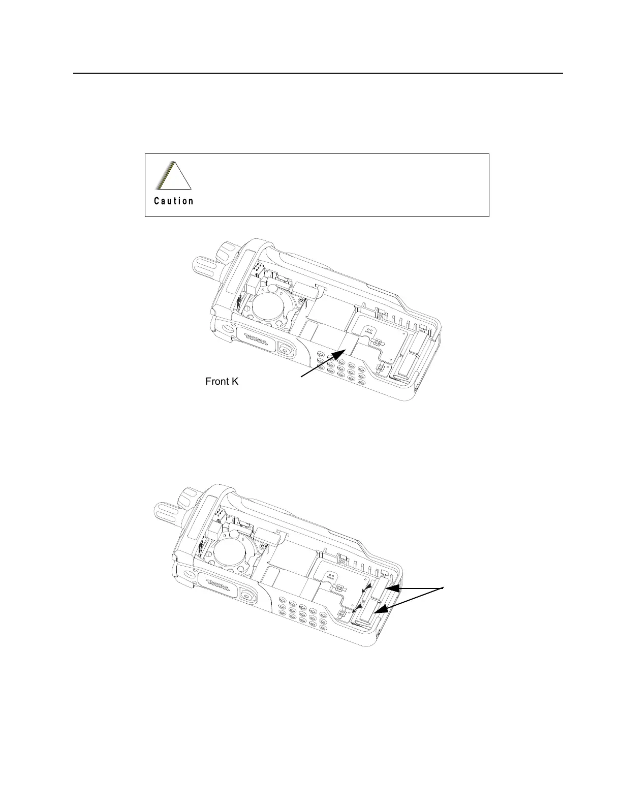
4. Gently plug in the connectors of the Back Kit Flex (43) to the Keypad Board (35) as shown in
Figure 8-39.
Figure 8-39. Plug in the Back Kit Flex Connectors
NOTE: Plug in the connectors at the side of the Back Kit Flex which reads “To Keypad Board”.
When plugging in the connectors, care is needed to avoid
damage to the interconnect and surrounding on-board
components.

 Loading...