6878215A01
Standard Configurations: Planning the Installation 2-3
2.1.2 Wiring Diagrams
Figure 2-4 through Figure 2-11 show the wiring diagrams for all the possible configurations. The title
under each figure identifies the O3, O5 or O9 control head configurations. Identify which of these
figures shows the configuration that you are installing, and use the diagram when planning the
installation.
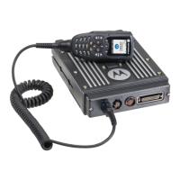
Figure 2-4. Radio Installation (O5 Mid Power Dash Mount)
NOTE: In dash mount configuration, it is mandatory that a rear accessory cable be attached at the
back of a mid power transceiver, in order to ground the Emergency pin to GND. Or, an
emergency footswitch or pushbutton switch must be attached at the back of a mid power.
If the emergency pin is not grounded, upon the attachment of the A+ cable at the DC
connector, the radio will detect a HIGH for the emergency pin state, and assume that
emergency has been activated. This will attempt to power on the radio, and will result in
excessive current draw and incorrect radio operation. Refer to Section 2.1.3.1 for further
details and recommended wiring of emergency in dash mount.
BATTERY
HORN
RELAY
LIGHT
RELAY
MIC
CLIP
SPEAKER
MIC
EMERGENCY
SWITCH
FUSE
FUSE
BLOCK
(+)
(-)
RED LEAD
FUSE
FIREWALL
HOLE
MOUNTING
SCREW
DASH MOUNT RADIO
ANTENNA
CONNECTION
ANTENNA 1
3 ft
IGN SENSE (ACC)
P2
(SEE J2
PINOUT)
DC
POWER
CABLE
TRUNNION
J2
REAR ACCESSORY CONNECTOR
1
7
8
14
13
20
21
26
SPKR-
SPKR+
VIPOUT 2
12V
(RELAY)
VIPOUT 1
12V
(RELAY)
GROUND
EMERGENCY
IGN SENSE
(ACC)
ANTENNA
CONNECTION
ANTENNA 2
(FOR DUAL
BAND RADIOS)
ANTENNA
CONNECTION
ANTENNA 3
GPS (OPTIONAL)
3 ft
 Loading...