6878215A01
2-10 Standard Configurations: Planning the Installation
RADIO COMPARTMENT
OPERATOR COMPARTMENT
VEHICLE BATTERY
COMPARTMENT
Siren Box
CAUTION
(BLK)
A+
(Red)
A+
(Red)
15A Fuse
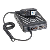
MICROPHONE
VEHICLE
IGNITION SWITCH
VEHICLE
BATTERY
PART OF
VEHICLE
WIRING
Siren Speaker
ON/ACC
3A OR 4A FUSE
SEE NOTE
SPEAKER
RADIO POWER CABLE
(RED/BATTERY HOT)
15A, 20A OR
30A FUSE
16A Circuit Breaker
GROMMET
GROMMET
GROMMET
REAR
CONNECTOR
URC Controller
Box
Chassis GND
GCAI to RJ45
Cable
RADIO
TIB
Chassis GND
CAN extension cable
A+
(Red)
IGN Sense
(yellow)
(BLK)
Control Head (Rear View)
Chassis GND
(+)
(-)
Figure 2-15. Cabling Interconnect Diagram for 09 Remote Mount (URC is optional.)
NOTE:
For remote mount configurations, do not supply IGNITION at the radio's rear accessory connector. IGNITION should be supplied according to TABLE 2-2. See TABLE 2-2 for combinations of wiring th
RED and YELLOW cables.
The RED and YELLOW power cables connect to either the vehicle battery or the ignition switch. Connect the RED cable directly to the battery. The receiver operates when the control head is on. Conne
the YELLOW cable to the ignition switch. The transmitter operates only when the ignition switch is on.
Alternate connections: Connecting both RED and YELLOW cables to the battery allows the control head to turn the receiver and transmitter on or off. Connecting both RED and YELLOW cables to th
ignition switch allows the ignition switch to turn the receiver and transmitter on or off. Alternator whine and other noise problems may occur. Isolate the RED cable with a Motorola relay (5900813674).
 Loading...