6881076C25-D October 28, 2002
Troubleshooting Procedures: Power Amplifier Procedures 4-23
If it is verified that both power set and current limit are not related to the power problem, then the
synthesizer output must be checked. A milliwatt meter connected to the TX injection cable should
indicate at least 10 mW of injection power during key-up. If this is not the case, refer to the RF board
and VCO sections of this manual for troubleshooting procedures.
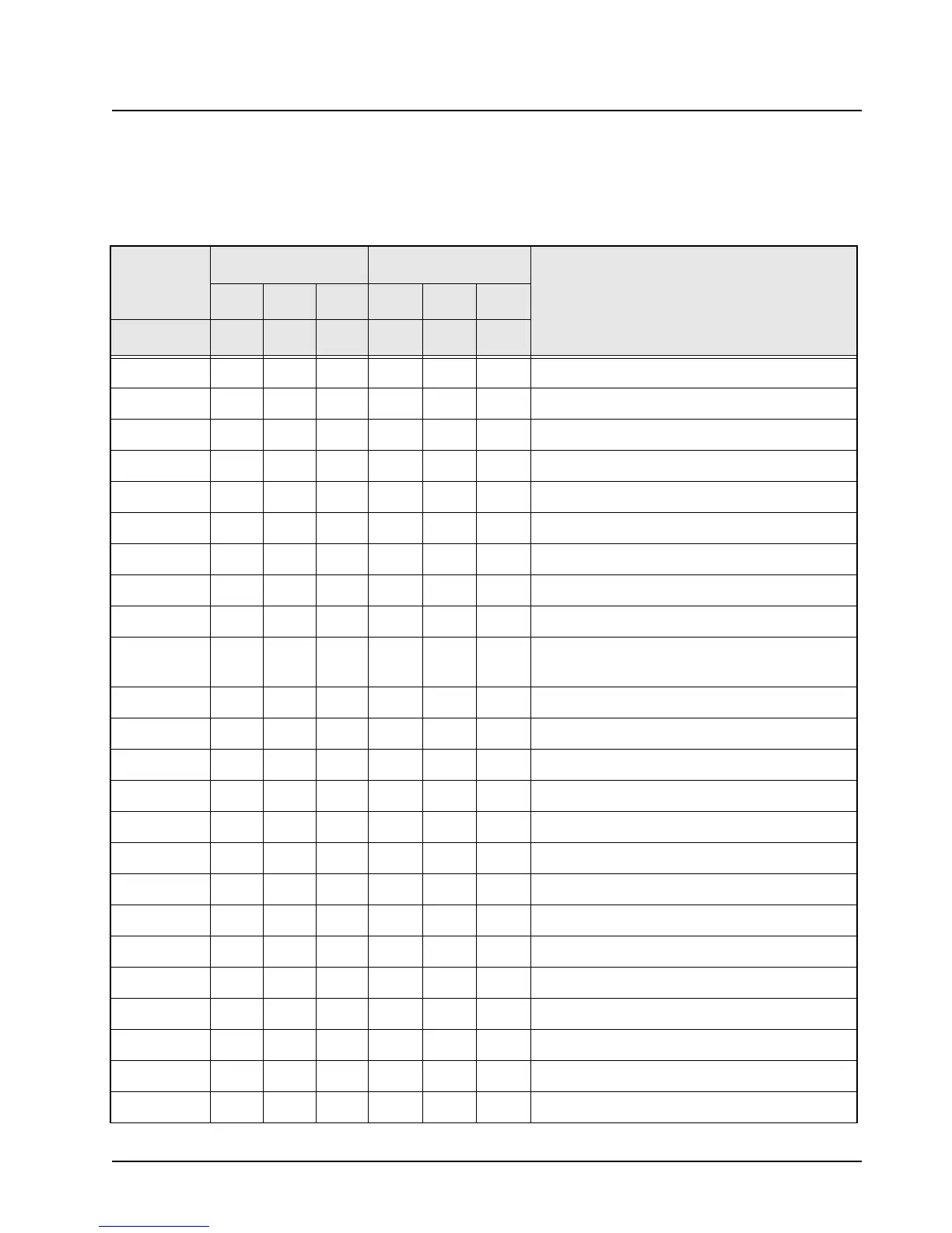
Table 4-8. Power Control DC Voltage Chart
LOCATION
RX MODE TX MODE
COMMENTS
LOW TYP HI LOW TYP HI
J1
1002.03.2
Control Voltage Limit
2 0 2.0 7.0 10.0
Drive Voltage
3 10.8 13.6 16.5 10.0 13.0 16.0
Current Sense +
40009.29.49.8
Keyed 9.4
5 10.8 13.6 16.5 10.0 13.0 16.0
A+ to Command Board
60 1.2
Temp Sense (cutback begins at 3.3-V)
7------
Key (no pin)
8 0 13.0 9.3 5.0
Forward Detect Voltage
9 10.8 13.6 16.5 10.0 13.0 16.0
A+ to Command Board
10
11
9.4
10.8
9.6
13.6
9.9
16.5
9.4
9.8
9.6
12.8
9.9
15.8
9.6-V Supply from Command Board
Current Sense - (voltage delta 150 mV)
12 - - - - - -
Key (no pin or wire)
U500
1000000
Ground
20 3.2
Control AMP Input
3000000
Control AMP Input (not used)
40023.2
Control Voltage Limit (cutback at 3.3 V)
59 0
N.C.
6 1.5 3.0 4.5 1.5 3.0 4.5
Power Set from D-A (max power at 1.5 V)
701.53.04.5
Power Set Buffer Out
801.33.56.0
Coupler Buffer Out
901.33.56.0
Forward Detect Volt
10 0 0
Reflected Power Detect (not used)
11 0 1.3 3.5 6.0
Same as pin 8 (not used)
12 0 0 1.2 6.0
Thermister Buffer out (increases as PA gets hot)

 Loading...


