5-14 Troubleshooting Charts
October 28, 2002 6881076C25-D
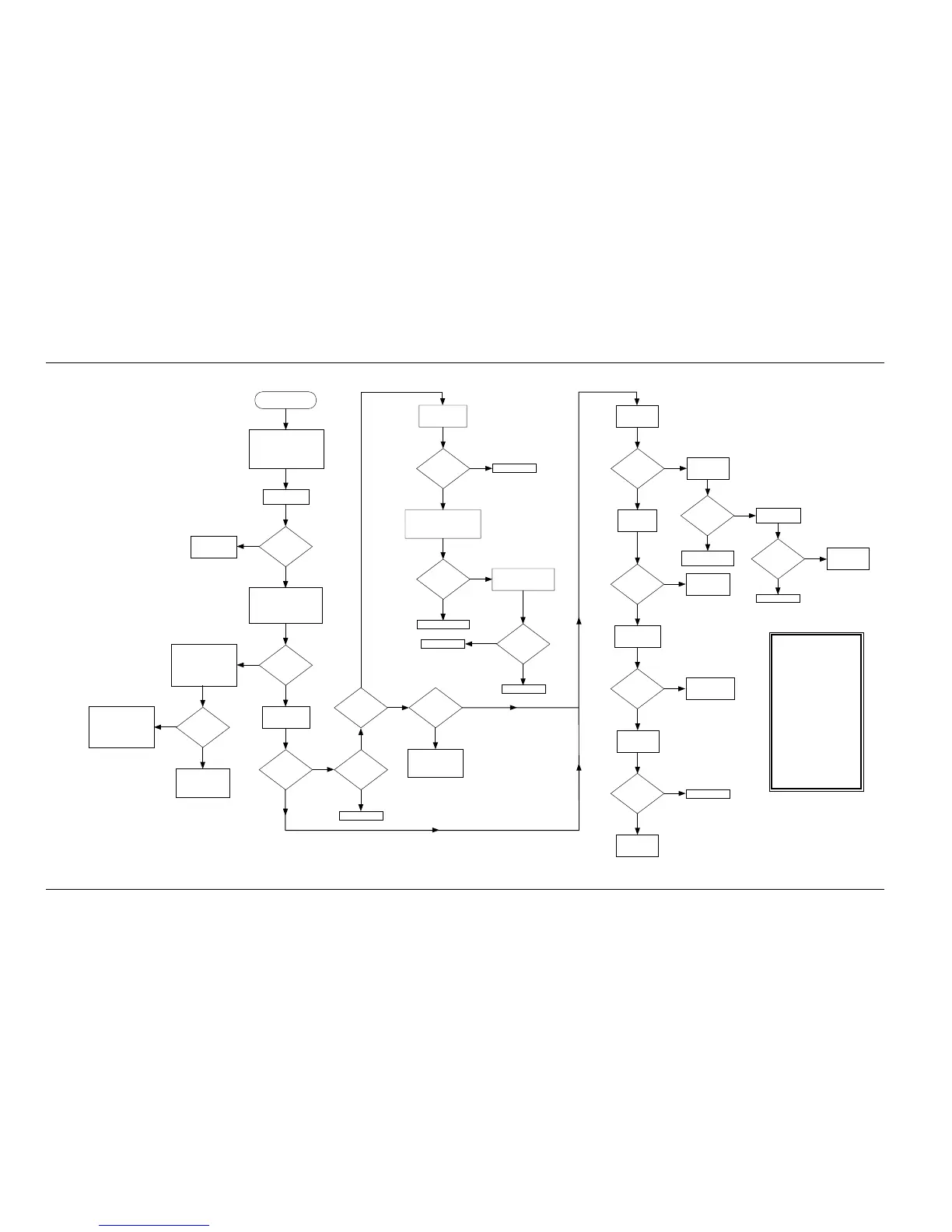
Chart C.19 No RX Audio
Synopsis
This failure indicates a lack of
received audio with the fault lying
with the VOCON or Command
board. It assumes a functional
transceiver and no power
up fail codes were displayed.
Since all received signal modes
occur through this same path,
this failure applies to digital/
PL,DPL, etc. Failure modes are
as follows:
1) Missing DSP IRQB interrupt.
2) Lack of 2.4 REF clock and/or
data from ABACUS.
3) Missing clock or data on SSI
port from ADSIC.
4) Non-functional control of or
faulty Audio PA.
5) Faulty ADSIC.
No Receive Audio
Set radio to test mode CSQ.
Inject a 1KHz modulated
signal at the carrier.
Frequency at -60dBm level
with 3KHz deviation.
Verify signal
at output of
U524 pin 2.
Signal
present?
Verify signal
at input of
U524 pin 1.
Signal
present?
Verify signal
present at
U450 pin 2.
Signals
present?
Signal
present?
Signals
present?
Check for
continuity from
U524 to U450.
Repair connection
from C412 to U524.
Verify control
lines to U524.
Troubleshoot
control or
supply lines.
Signals
present?
Replace U524.
Verify signals
present at U450
pins 11 and 13.
Replace U450.
Troubleshoot
control or
supply lines.
Verify control
and supply
for U450.
Repair connection
from U450 to
speaker terminals.
MAEPF-26075-O
Yes
No
Yes
No
Yes
No
No
No
No
No
No
Yes
No
Yes
Verify signals per
Fig. W2 at points
indicated.
Signals
present?
Replace U406.
Check for continuity between
U405 and U406 of the
signals depicted in Fig. W2
and the 8KHz IRQB.
No
Yes
Alert tone
audible?
Perform radio functions,
which causes an alert
tone to be generated.
Replace U405.
Replace U406.
No
Yes
Connections
good?
Repair connections.
Yes
Standard
bias OK?
No
Yes
No
Yes
Signals
present?
No
Yes
Signals
present?
Yes
Yes
No
Fig. W7-
Trace 1
present?
Fig. W7-
Trace 2
present?
Fig. W7-
Trace 3 or 4
present or in
phase?
Yes
Yes
Verify standard
bias per Table 6.
Isolate and
repair problems,
See Chart C.5.
Verify signals present at
ADSIC (U406) per Fig. W10
and Fig. W5. Note DOUT
and DOUT* are low-level
voltage signals.
During a mode change,
verify an ABACUS
programming sequence
occurs per Fig. W4,
probing on the
ABACUS carrier.
Verify signals per
Fig. W7 at points
indicated.
ABACUS is
programmed?
No
Yes
Verify SBI signal
connection between
ADSIC and ABACUS
ICs; repair as necessary.
If connection is good
replace U406.
Fault lies with RF
board. Refer to
appropriate section,
Chart C.1.
Replace U406.
Check for continuity
from U406 to C412.
Check for shorts and
check C412.

 Loading...


