Troubleshooting Charts 5-25
6881076C25-D October 28, 2002
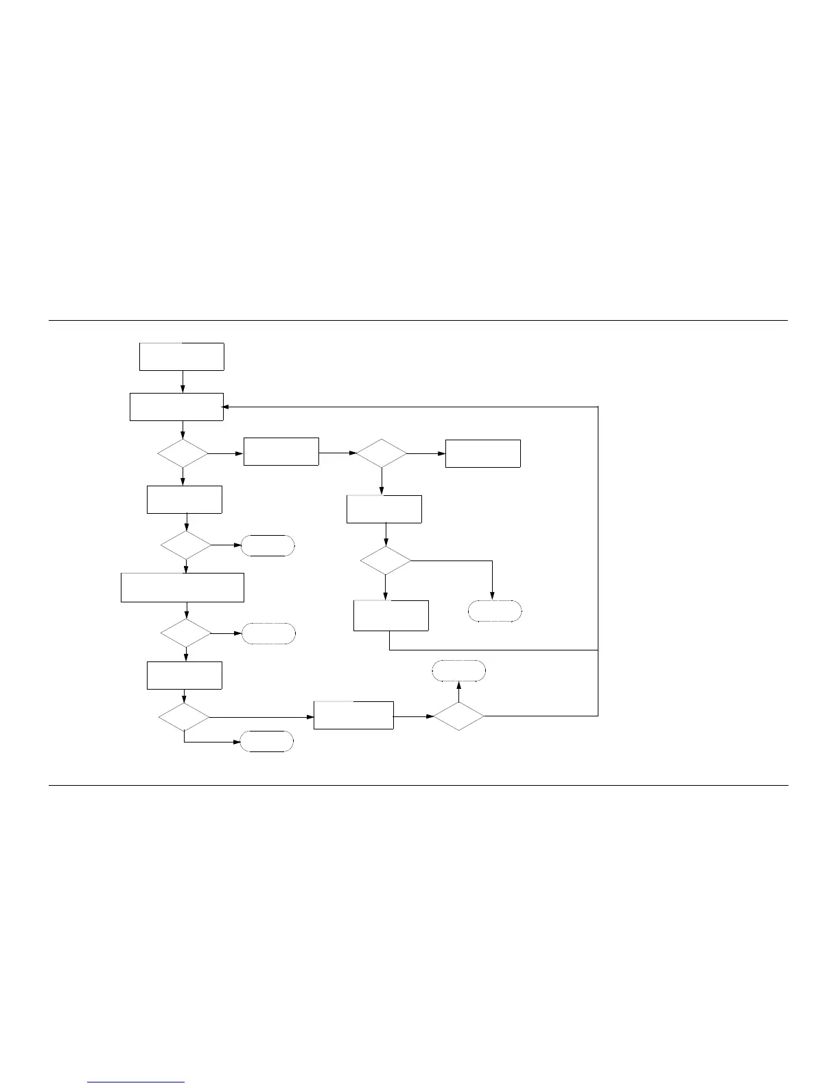
Chart C.32 ASTRO Spectra Plus VOCON Secure Hardware Failure
Measure the voltage at pins 1, 2
and 20 on the secure connector.
The voltage reading should be
between 10V and 13V
Voltages
correct?
Make sure the Secure Module
is connected to the Plus VOCON
board and the radio is ON
Measure voltage on Q600,
pin 5. Voltage should read
between 10V and 13V
Measure waveforms on P1
(secure connector) at pins
7, 8, 9, and 10. They should
look similar to Figure 6-21
Waveforms
correct?
No trouble
found
Measure waveforms on U502 (pins 11, 13, and
15) and U504 (pin 9). They should look similar to
Figure 11 but with an amplitude of approximately
3V
Waveforms
correct?
Verify placement
and soldering of
U502 and U504
Measure waveform on U601
pin 5. It should look like
Figure 6-22
Waveforms
correct?
Verify placement,
soldering of Patriot
IC- U300
Verify placement and soldering
of the following components:
U307, U601, U600, and U602
Waveforms
correct?
Refer board
to Service Depot
Verify placement, soldering
of Q600. Otherwise replace
part
Voltage
correct?
Verify placement,
soldering of Patriot
IC- U300
Measure voltage on Q600
pin 4. It should measure 0V
Verify placement, soldering
of J501 connector
Voltage
correct?
Yes
No
Yes
Yes
Yes
NoNo
No
Yes
No
Yes
Yes
No
No

 Loading...


