7-48 Schematics, Component Location Diagrams and Parts Lists: VOCON Section
September 5, 2008 6881076C25-E
Notes:
1. For optimum performance, order replacement diodes, transistors, and circuit
modules by Motorola part number only.
2. When ordering crystals, specify carrier frequency, crystal frequency, crystal
type number, and Motorola part number.
3. Part value notations:
p=10
-12
n=10
-9
µ=10
-6
m=10
-3
k=10
3
M=10
6
4. ITEM refers to the component reference designator. SIDE refers to the loca-
tion of the component on the board; S1=Side 1, S2=Side 2.
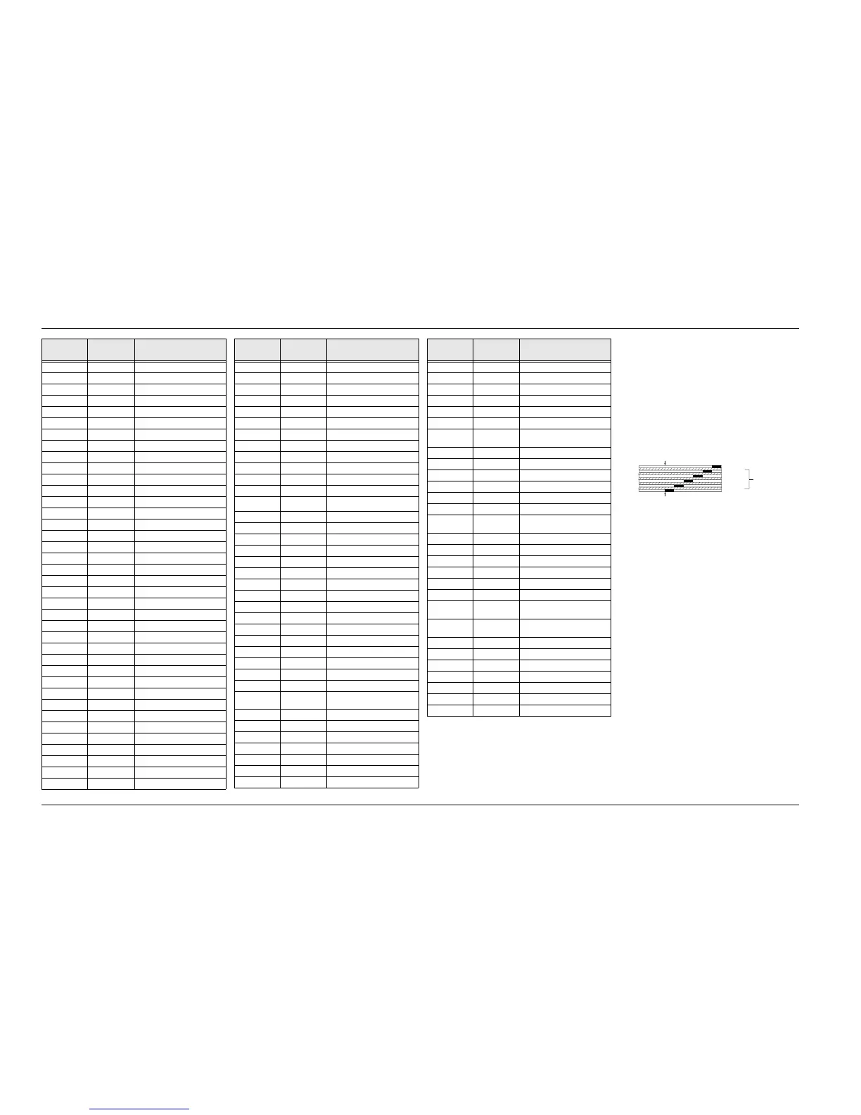
5. The VOCON Board Kit uses a 6-layer printed circuit board.
R251 0662057B47 0
R252 0662057A97 100k
R253 thru 256 – Not Placed
R257 thru 260 0662057A97 100k
R261 0662057A73 10k
R262 0662057A89 47k
R263 – Not Placed
R264 0662057A82 24k
R265, 266 0662057A97 100k
R267 0662057A73 10k
R268 0662057A97 100k
R269 0662057A85 33k
R270, 271 0662057A97 100k
R272 0662057A73 10k
R273 0662057A97 100k
R274 – Not Placed
R275 thru 282 0662057A85 33k
R283 – Not Placed
R284 0662057A97 100k
R285 thru 287 – Not Placed
R288 0662057A97 100k
R289 thru 307 – Not Placed
R308 0662057B47 0
R400, 401 0662057A73 10k
R402 0662057B12 390k
R403 – Not Placed
R404 0662057A73 10k
R405 0662057B22 1M
R406 – Not Placed
R407 0662057A97 100k
R408 – Not Placed
R409 thru 411 0662057A73 10k
R412 0662057A65 4.7k
R413, 414 0662057A73 10k
R415 0662057A97 100k
R416 – Not Placed
R417 0662057A97 100k
R418 0662057A49 1k
ITEM
MOTOROLA
PART N UMBER
DESCRIPTION
R419 0662057A73 10k
R420 0662057A97 100k
R421 thru 423 – Not Placed
R424 0662057A63 3.9k
R425 0662057A69 6.8k
R426 thru 431 – Not Placed
R432 0662057A73 10k
R433 0662057A57 2.2k
R434 – Not Placed
R435 0662057A73 10k
R436 thru 438 – Not Placed
R436 thru 438 – Not Placed
R439 0662057A73 10k
R440 – Not Placed
R441 0662057A73 10k
R442, 443 – Not Placed
R444 0662057A73 10k
R445 – Not Placed
R450 0662057A89 47k
R459, 460 0662057A73 10k
R467 – Not Placed
R477 thru 480 – Not Placed
R481 0662057A97 100k
R482 0662057B47 0
R483 thru 485 0662057A97 100k
R486 – Not Placed
R490 thru 492 – Not Placed
R499 0662057A73 10k
INTEGRATED CIRCUIT
MODULE: See Note 1.
U201 5105109Z72 32k x 8 EEPROM
U202 5185748L01 SRAM (Static RAM), 32k x 8
U204 5113802A75 Microprocessor
U205 5185963A84 FLASH
U206 5185765B19 SLIC (Support-Logic IC)
U208 – Not Placed
U211 5105279V65 AND Gate
ITEM
MOTOROLA
PART NUMBER
DESCRIPTION
U214 5105279V65 AND Gate
U215, 216 5105750U28 Switch, Bilateral CMOS
U401 – Not Placed
U402, 403 5185963A18 8k x 24 DSPRAM
U404 5105130C54 FLASH ROM, 256k x 8
U405 5105457W66 DSP (Digital Signal Processor)
U406 5185963A10 ADSIC (ABACUS/DSP Support
IC)
U407 5105492X73 Voltage DetectorXSX
U408 thru 412 – Not Placed
U414 5185963A18 8k x 24 DSPRAM
U417 – Not Placed
DIODE: See Note 1.
VR201 thru
203
4813830A15 Zener, 5.6V
VR204, 205 – Not Placed
VR206 4813830A31 Zener, 18V
VR207 4813830A22 Zener, 9.1V
VR208 4813830A24 Zener, 11V
VR209 4813830A15 Zener, 5.6V
VR210 – Not Placed
VR211 thru
214
4813830A15 Zener, 5.6V
VR215 thru
223
– Not Placed
CRYSTAL: See Note 2.
Y201 4805574W01 7.3728MHz
Y401 4805573W01 33MHz
MISCELLANEOUS:
8405160Y04 Printed Circuit Board
ITEM
MOTOROLA
PART N UMBER
DESCRIPTION
LAYER 1 (L1)
LAYER 2 (L2)
LAYER 3 (L3)
LAYER 4 (L4)
INNER LAYERS
LAYER 5 (L5)
LAYER 6 (L6)
MAEPF-18827-A
SIDE 1
SIDE 2
6-LAYER CIRCUIT BOARD DETAIL VIEWING
COPPER STEPS IN PROPER LAYER SEQUENCE

 Loading...


