13-68
NCN6167C Controller Board
Electrical Parts List
Notes:
1. For optimum performance, order replacement diodes, transistors, and circuit
modules by Motorola part number only.
2. When ordering crystals, specify carrier frequency, crystal frequency, crystal
type number, and Motorola part number.
3. Part value notations:
p=10
-12
n=10
-9
µ=10
-6
m=10
-3
k=10
3
M=10
6
4. ITEM refers to the component reference designator. SIDE refers to the location
of the component on the board; S1=Side 1, S2=Side 2.
5. The NCN6167 Controller Bd Kit uses an 8-layer printed circuit board.
ITEM
MOTOROLA
PART NUMBER
DESCRIPTION
CAPACITOR, Fixed: pF ±5%; 50V
unless otherwise stated
C100 thru C106 2113931F17 470
C108 2113930F39 33
C109 thru C111 2113931F17 470
C112 2113930F39 33
C113, C114 2113931F17 470
C116 2113930F39 33
C117 2113931F17 470
C118 2113930F39 33
C120, C121 2113930F39 33
C122 2113931F17 470
C123, C124 2113930F39 33
C125 thru C138 2113931F17 470
C140 2113931F17 470
C142, C152 2113931F17 470
C160 2113932K15 0.1 µF +80/-20% 16V
C161 2113930F31 15
C162 ----------------- Not Placed
C163 2113930F31 15
C164, C165 2113932K15 0.1 µF +80/-20% 16V
C167 2113931F17 470
C168 thru C172 2113932K15 0.1 µF +80/-20% 16V
C175 2311049C05 47 µF
C176 2113932K15 0.1 µF +80/-20% 16V
C177 2113931F49 10 nF
C178 ----------------- Not Placed
C179 2113932K15 0.1 µF +80/-20% 16V
C180 2311049C07 100 µF 10V 10%
C182 2113931F17 470
C183 thru C186 2311049J12 4.7 µF
C187 2113932E20 0.1 µF 10% 16V
C188 2311049J12 4.7 µF
C189 2113932E20 0.1 µF 10% 16V
C190, C191 2113930F51 100
C191 2113930F51 100
C192 2113743A19 0.1 µF
C193, C195 2113743A23 0.22 µF
C196, C197 0662057R60 10k
C198 2113931F49 10 nF
C199, C200 2113743A23 0.22 µF
C201 2311049J12 4.7 µF
C202 2113931F41 4.7 nF
C203, C204 2113932K15 0.1 µF +80/-20% 16V
C205, C206 2113743F12 0.33 µF
C207 thru C209 2311049A07 1 µF
C210 0662057R54 6.81k
C211 2113743A23 0.22 µF
C212, C213 2113932K15 0.1 µF +80/-20% 16V
C214 2311049A05 0.47 µF
C215, C217 2113932K15 0.1 µF +80/-20% 16V
C219, C220 2113932K15 0.1 µF +80/-20% 16V
C223 2113931F17 470
C224 2113930F39 33
C225, C226 2113931F17 470
C227, C228 2113930F39 33
C229 2113931F17 470
DIODE: See Note 1
D100, D101 4884939C35 Hot Carrier, 4V
D104 4813833B09 Schottky, 30V
D105 4884939C35 Hot Carrier, 4V
JACK:
J101 0980423L02 Controls Flex Assembly Connector
J401 ----------------- Not Placed
J601 0913915A11 Encryption Board Connector
COIL, RF: unless otherwise stated
L100 thru L115 2462587Q40 270 nH
L117, L118 2462587Q40 270 nH
L119 2485853A01 68 µH
L120 2460578C43 33 µH
L500 2462587Q40 270 nH
L501 2405688Z01 Ferrite Bead
CONTACT:
M1, M2 3985951A01 Antenna Ground
PLUG:
P107 ----------------- Not Placed
P201 ----------------- Not Placed
P301 ----------------- Not Placed
TRANSISTOR: See Note 1.
Q102 4805128M12 NPN
Q104, Q105 4805128M12 NPN
Q106 4805718V01 MOSFET Switch
Q107 4880048M01 NPN
Q108 ----------------- Not Placed
Q109 4805128M12 NPN
Q110 4805128M40 PNP
Q111, Q112 4805921T09 Dual NPN
Q113 ----------------- Not Placed
RESISTOR, Fixed: Ω ±5%; 1/8W
unless otherwise stated
R100 0662057A65 4700
R101 0662057A89 47k
R102 0662057A36 300
R103 0662057A35 270
R105 0662057A62 3.6k
R106 0662057A97 100k
R108 0662057A97 100k
R109 0662057A73 10k
R110 thru R112 0662057A39 390
R114 0662057A49 1k
R115 0662057A39 390
R116 thru R118 0662057A97 100k
R119 thru R123 0662057A49 1k
R124 0662057A85 33k
R125, R126 0662057A97 100k
R127 0662057A49 1k
R128 0662057B47 0
R129, R133 0662057A49 1k
R135, thru R143 0662057A85 33k
R144 thru R152 0662057A49 1k
R153 thru R155 0662057A97 100k
R156 0662057A73 10k
R157 0662057B47 0
R158 0662057B22 1 M
R159, R160 0662057A65 4.7k
R161 0662057A73 10k
R163 0683962T45 68
R164 0662057A73 10k
R165 0662057A57 2.2k
R167 0662057A97 100k
R168 0662057A65 4.7k
R169 0662057A97 100k
R170 0662057G08 82.5k 1%
R171 0662057A97 100k
R172 0662057R92 47.5k 1%
R173 0662057B47 0
R174, R175 0662057A73 10k
R176, R177 0662057A97 100k
R178 0662057A85 33k
R179 0662057A65 4.7k
R180 0662057A97 100k
R181 0662057B47 0
R182, R183 0662057A97 100k
R184, R185 0662057A73 10k
R186 ----------------- Not Placed
R187 thru R189 0662057A97 100k
R190 0662057A73 10k
R191 0662057A49 1k
R192 ----------------- Not Placed
R193 0662057A39 390
R194 0662057A59 2.7k
R195 0662057A81 22k
R196 0662057B02 150k
R197 0662057A39 390
R198 0662057A57 2.2k
R199 0662057G14 110
R200 0662057A81 22k
R201 0662057B02 150k
R202 0662057G08 82.5k
R203, R204 0662057A73 10k
R205, R206 ----------------- Not Placed
R207 0662057A80 20k
R208 0662057A97 100k
R209 0662057A65 4.7k
R211, R212 0662057A73 10k
R213 thru R215 ----------------- Not Placed
R216, R217 0662057B47 0
R502 0662057A97 100k
R503 0662057A65 4.7k
R504 0662057A97 100k
R507, R508 0662057A97 100k
R509 0662057C03 1
R510 0662057B47 0
R513, R514 0662057A39 390
R515 0662057A97 100k
R516 0662057A49 1k
R517 0662057A23 82
R518 0662057A39 390
R519, R520 0662057A97 100k
R521 0662057A25 100
R529 0662057A97 100k
R531 ----------------- Not Placed
R533 ----------------- Not Placed
R535, R536 0662057A97 100k
R537 0662057C03 1
R538 ----------------- Not Placed
R539 0662057A73 10k
R540 ----------------- Not Placed
R541 0662057B47 0
R542 ----------------- Not Placed
INTEGRATED CIRCUIT MODULE:
See Note 1.
U701 5113802A75 HC11F1 MCU (QFP)
U702 5185765B19 SSLIC (OMPAC)
U704 5105750U28 CMOS Switch (MUX)
U705 5185748L01 32k x8 SRAM
U706 5105109Z72 32k x 8 EEPROM
U708 5105279V65 AND GATE
U709 5105109Z36 5V Digital Switching Regulator
U710 5105625U41 5V Analog Regulator
U712, U713 5105750U28 CMOS Switch (MUX)
U714 5105364W01 DUAL OP-AMP
U717 5105750U28 CMOS Switch (MUX)
U718 5105457W68 Audio PA (QFP)
U725 5105279V65 AND GATE
U726 5105492X73 4.2V Voltage Detector
U727 5105109Z25 1M x 8 FLASH ROM
U728, U729 5105750U28 CMOS Switch (MUX)
DIODE: See Note 1.
VR100 thru
VR102
4813830A24 Zener 11V
VR104 4805117Y01 DUAL, 6.2V Zener
VR105 4813830A15 Zener, 5.6V
VR107 thru
VR109
4813830A24 Zener, 11V
VR110 4805117Y01 DUAL, 6.2V Zener
VR111 4813830A31 Zener, 18V
VR112 4813830A24 Zener, 11V
VR113 4813830A31 Zener, 18V
VR117 4813830A24 Zener, 11V
VR119 4813830A22 Zener, 9.1V
VR121 4813830A24 Zener, 11V
VR122, VR123 4813830A15 Zener, 5.6V
VR124 4805117Y01 DUAL, 6.2V Zener
VR300 4805117Y01 DUAL, 6.2V Zener
CRYSTAL: See Note 2.
Y100 4805574W01 7.3728 MHz
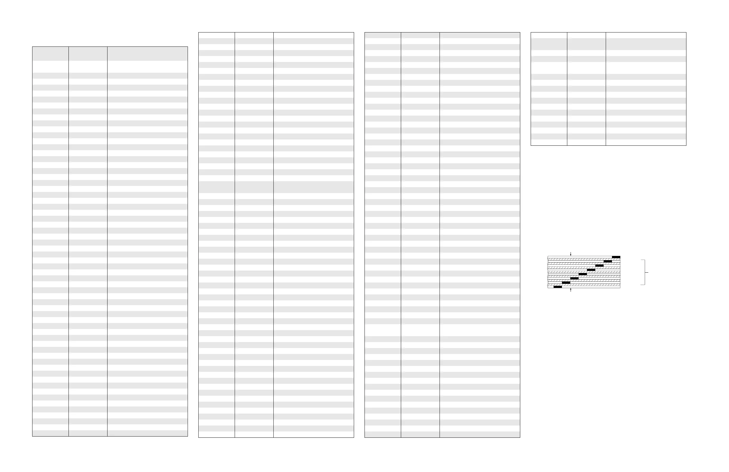
LAYER 1 (L1)
LAYER 2 (L2)
LAYER 3 (L3)
LAYER 4 (L4)
INNER LAYERS
LAYER 5 (L5)
LAYER 6 (L6)
MAEPF-18828-A
SIDE 1
SIDE 2
8-LAYER CIRCUIT BOARD DETAIL VIEWING
COPPER STEPS IN PROPER LAYER SEQUENCE
LAYER 7 (L7)
LAYER 8 (L8)

 Loading...


