3-2
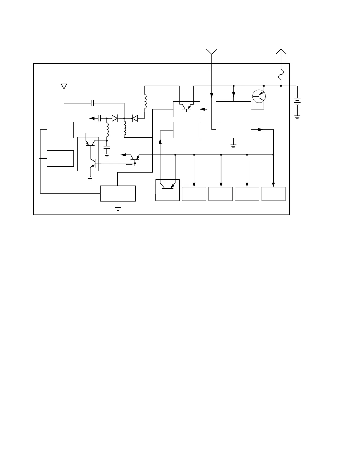
The switched B+ voltage supplies power to circuits on the transceiver
board. This voltage is applied to the 5-volt regulator (U202) via
decoupling component C302 to produce a stable 5.0-volt output. Raw
B+ (7.5V), which is connected to the ALC IC (U101), is switched
through the output (CATH1) to another 5-volt regulator (U106).
Regulator U202 supplies those circuits which need to remain on at all
times, such as the reference oscillator (U203), fractional-N synthesizer
(U204), D/A IC (U102), and the ABACUS IC (U401). The D/A IC
controls dc switching of the transceiver board. The SC1 signal at U102,
pin 12 controls transistors Q107, Q111, and the transmit 5 volts (T5).
The SC3 signal at U102, pin C4 controls the Rx 5V switch U106, and
the receive 5 volts (R5). A voltage on the synthesizer SOUT line at
U204, pin 19 supplies power (Vcc) to the VCO buffer at U201, pin 3.
During the receive mode, regulator U106 supplies regulated 5V (R5) to
the receiver front end. In the battery-saver mode, R5 can be switched
on and off by controlling pin 3 of U106. Module U106 is not used
during the transmit mode. During the transmit mode, transmit 5 volts
(T5) for the ALC IC and other TX circuitry is obtained from U202 via
switching transistor Q111.
Battery
7.5V
+
RF PA Module
U105
5V Regulator
U202
VCOB IC
U201
ALC U101
T5
L105
CR108
RX
L122
L121
Vcc
RF Amp
U1/Q1
Mixer
U2
Q107
R5
5V Regulator
U106
SB+
VHF/UHF Transceiver Board
MAEPF-25994-O
CR109
5V
S
Out
Fuse
To/From Controller Board
SW B+
UNSW B+
Raw B+
T5
RX/TX
Ref Osc
U203
ABACUS
U401
D/A IC
U102
Synth
U204
IF Amp
Q601
Figure 3-2 B+ Routing for VHF/UHF Transceiver Boards

 Loading...


