C24 Hardware Interface Manual
Version 0.3
2.6 Serial Interfaces
The module includes 3 completely independent serial communications interfaces, which may be used by
the application for several purposes.
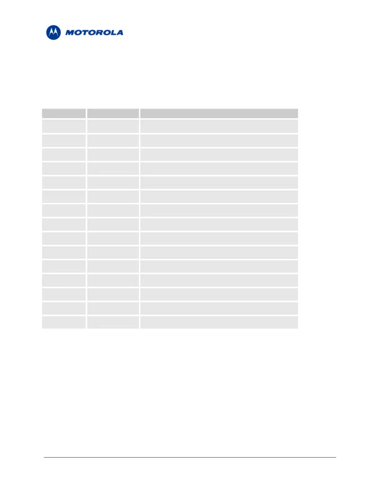
TABLE 5 – Serial Interfaces signals
Pin (s) Signal Name Description
9 RTS_N Primary UART “Ready -To - Send” signal
11 RXD_N Primary UART “Receive Data” signal
13 DSR_N Primary UART “Data - Set - Ready” signal
15 CTS_N Primary UART “Clear -To - Send” signal
17 DCD_N Primary UART “Carrier Detect” signal
19 DTR_N Primary UART “Data - Terminal - Ready” signal
21 TXD_N Primary UART “Transmit Data” signal
23 RI_N Primary UART “Ring Indicator” signal
29 RXD2 Secondary UART “Receive Data” signal
31 TXD2 Secondary UART “Transmit Data” signal
33 RTS2 Secondary UART “Ready -To - Send” signal
35 CTS2 Secondary UART “Clear -To - Send” signal
10 USB_VBUS USB bus power
12 USB_DP USB bus differential serial data (positive)
14 USB_DN USB bus differential serial data (negetive)
2.6.1 Primary UART (UART1)
The module’s primary UART is a standard 8-signal bus. The primary UART is used for all the
communications with the module – AT commands interface, Data Calls and CSD data, programming and
software upgrades.
The UART signals are active low CMOS level signals. For standard RS232 communications with a PC, an
external transceiver is required.
The module is defined as a DCE device, and the user application is defined as the DTE device. These
definitions apply for the UART signals naming conventions, and the direction of data flow, as described in
the following figure.
Motorola General Business Use
Page 17 of 36
 Loading...


