C24 Hardware Interface Manual
Version 0.3
2 Hardware Interface Description
The following sections describe in detail the Hardware Interface requirements and operation modes of the
C-Lite Module.
2.1 Operating Modes
The module should incorporate several operating modes. Each operating mode is different in the active
features and interfaces.
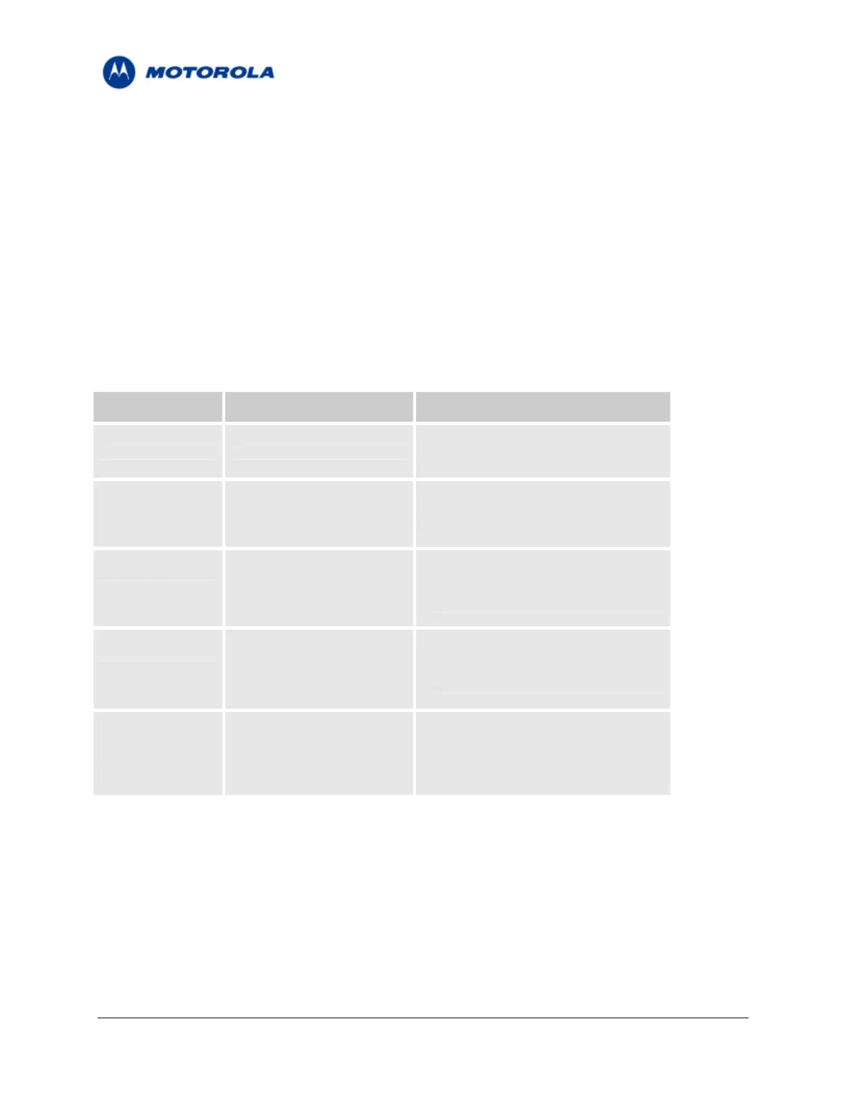
The following table summarizes the general characteristics of the module operating modes and provides
general guidelines for operation.
TABLE 1 – Module Operating Modes
Mode Description Features
Module is Off.
Not Powered VCC supply is disconnected
The interface signals are tri-stated.
Valid VCC supply,
The Module interface is tri-stated.
RTC Mode
RESET_N signal is enabled
Only the internal RTC timer is active.
(low).
RESET_N signal is disabled
The module is fully active and ready to
(high),
Idle Mode communicate.
CTS_N and DSR_N signals
This is the default power-up mode.
are enabled (low).
The module is in low power mode.
RESET_N signal is high,
Low power Mode The application interfaces are disabled,
CTS_N signal is disabled
but it continues to monitor the network.
A voice or data call is in progress.
RESET_N signal is high, When the call terminates, The Module
CSD or Data
TXEN_N signal is Low.
will return to the last operating state
(Idle or Sleep).
Motorola General Business Use
Page 7 of 36
 Loading...


