C24 Hardware Interface Manual
Version 0.3
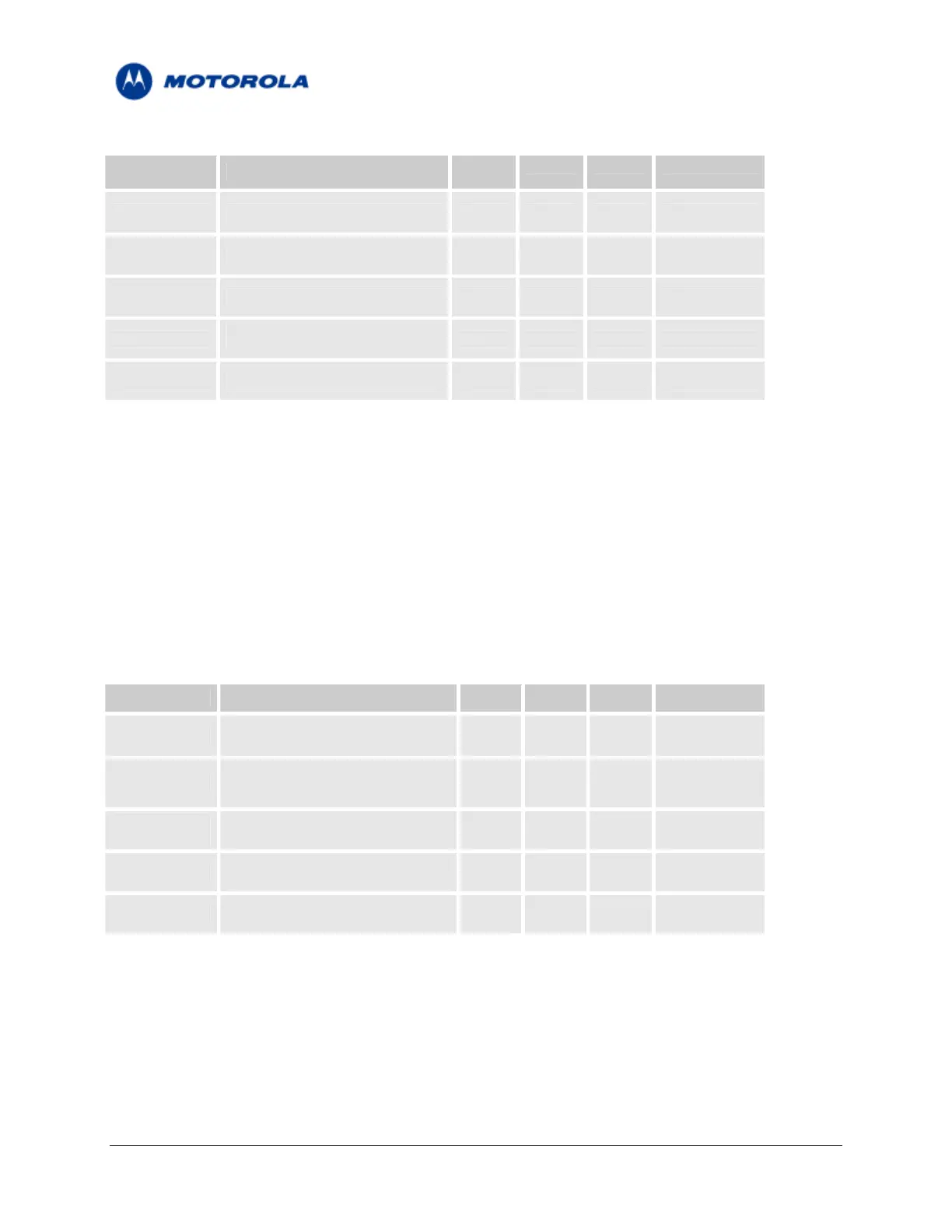
TABLE 8 – Microphone Port Specifications
Parameter Conditions Min
Typ Max Units
Input Voltage
No load 1.58 V
PP
Gain Programmable in 1 dB steps 0 31 dB
AC Input
1 KΩ
Impedance
R
BIAS
= 2 KΩ
Bias voltage 1.7 1.8 1.9 V
I
BIAS
≤ 1 mA
Bias Current 1 mA
2.8.2 Headset Microphone Port
The headset microphone port is designed for use with, but not limited to, a headset audio device. It is
located at pin 57 on the interface connector, named HDST_MIC.
It is designed as a single-ended input and should be referenced to the module analog ground.
The microphone input includes all the necessary circuitry to support a direct connection to a headset
microphone device. It incorporates an internal bias voltage of 1.8V through a 2.2KΩ resistor, and has an
impedance of 1KΩ.
TABLE 9 – Headset Microphone Port Specifications
Parameter Conditions Min
Typ Max Units
Input Voltage
No load 1.58 V
PP
Programmable in 1 dB steps
Gain 0 31 dB
AC Input
1 KΩ
Impedance
R
BIAS
= 2 KΩ
Bias voltage 1.7 1.8 1.9 V
I
BIAS
≤ 1 mA
Bias Current 1 mA
Motorola General Business Use
Page 22 of 36
 Loading...


