C24 Hardware Interface Manual
Version 0.3
2.8 Audio Interface
The module supports the following audio devices:
Two single-ended biased analog microphone inputs for use in a variety of modes.
Two differential mono analog speaker outputs for use in a variety of modes.
A digital serial interface using PCM coding.
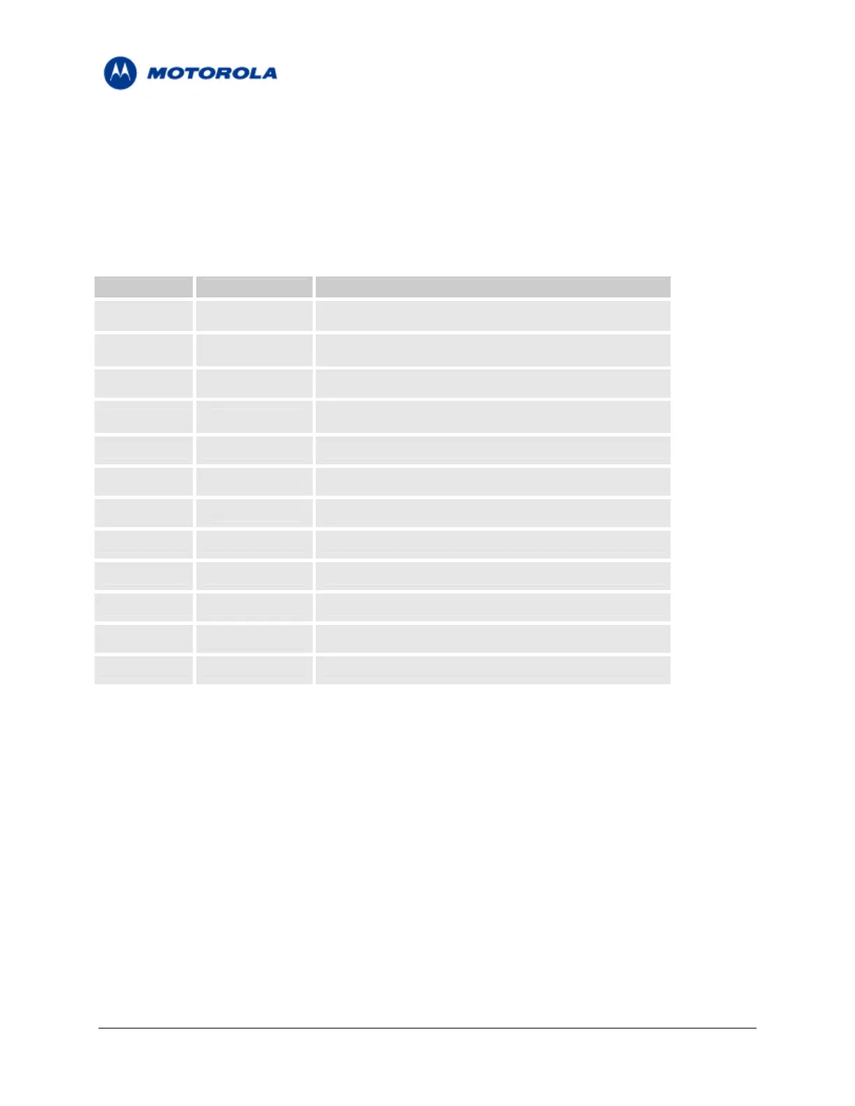
TABLE 7 – Audio Interface signals
Pin (s) Signal Name Description
55 HDST_INT_N Headset detection signal
57
Headset microphone signal / Differential Microphone
HDST_MIC
(positive)
59 AGND Audio Ground
Handset microphone signal / Differential Microphone
61 MIC
(negative)
63 ALRT_N Differential Loud speaker (negative)
65 ALRT_P Differential Loud speaker (positive)
67 SPKR_N Handset differential speaker (negative)
69 SPKR_P Handset differential speaker (positive)
18 PCM_DIN Digital audio receive
20 PCM_DOUT Digital audio transmit
22 PCM_CLK Digital audio clock
24 PCM_FS Digital audio frame sync.
2.8.1 Handset Microphone Port
The handset microphone port is the module’s power-up default active audio input for voice calls. It is
located on pin 61 at the interface connector, named MIC.
It is designed as a single-ended input and should be referenced to the module analog ground.
The microphone input includes all the necessary circuitry to support a direct connection to an external
microphone device. It incorporates an internal bias voltage of 1.8V through a 2.2KΩ resistor, and has an
impedance of 1KΩ.
Motorola General Business Use
Page 21 of 36
 Loading...


