Chapter 3
VHF1 PCB/SCHEMATICS/PARTS LISTS
1.0 Allocation of Schematics and Circuit Boards
1.1 VHF1 (136-162MHz)
The VHF circuits are contained on the printed circuit board (PCB) which also contains the Controller
circuits. This Chapter shows the schematics for the VHF circuits, the Controller circuits are
contained in Section 2 of this manual. The PCB component layouts and the Parts Lists in this
Chapter show both the Controller and VHF circuit components. The VHF schematics and the related
PCB and parts list are shown in the table below.
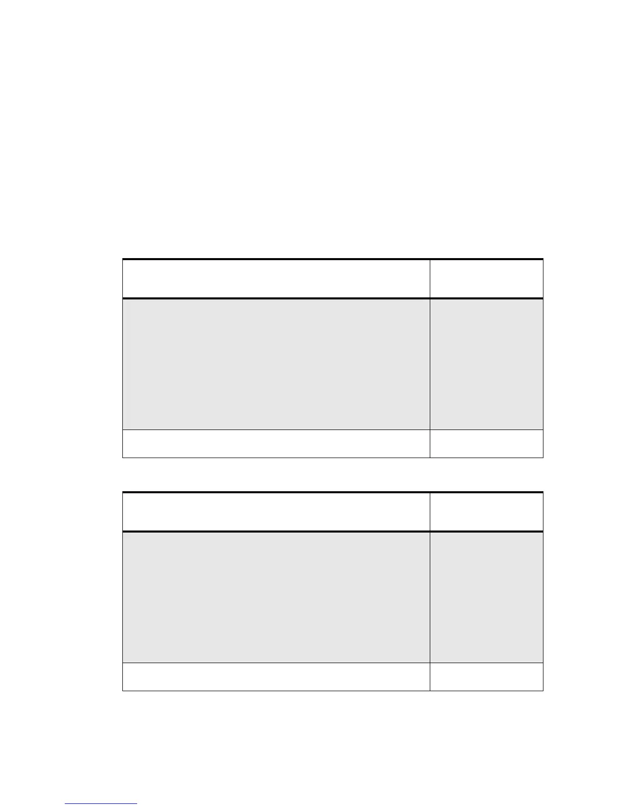
Table 3-1 VHF1 Diagrams and Parts Lists
PCB :
8486769Z02-A Main Board Top Side
8486769Z02-A Main Board Bottom Side
Page 3-3
Page 3-4
SCHEMATICS
Radio Circuit Block Diagram
Receiver Front End
Receiver Back End
Synthesiser
VCO
Transmit and Power Control Cct
Controller Interconnect Schematic Diagram
Microprocessor Circuitry Schematic Diagram
Audio Circuitry Schematic Diagram
DC Regulation Schematic Diagram
Page 3-5
Page 3-6
Page 3-7
Page 3-8
Page 3-9
Page 3-10
Page 3-11
Page3-12
Page3-13
Page3-14
Parts List
8486769Z02-A Page 3-15
PCB :
8486769Z04-C/Z05-D Main Board Top Side (EPP)
8486769Z04-C/Z05-D Main Board Bottom Side (EPP)
Page 3-19
Page 3-20
SCHEMATICS
Radio Circuit Block Diagram
Receiver Front End
Receiver Back End
Synthesiser
VCO
Transmit and Power Control Cct
Controller Interconnect Schematic Diagram
Microprocessor Circuitry Schematic Diagram
Audio Circuitry Schematic Diagram
DC Regulation Schematic Diagram
Page 3-21
Page 3-22
Page 3-23
Page 3-24
Page 3-25
Page 3-26
Page 3-27
Page 3-28
Page 3-29
Page 3-30
Parts List
8486769Z04-C/Z05-D Page 3-31

 Loading...


