2-4 TROUBLESHOOTING TABLES
3.0 Troubleshooting Table for Transmitter
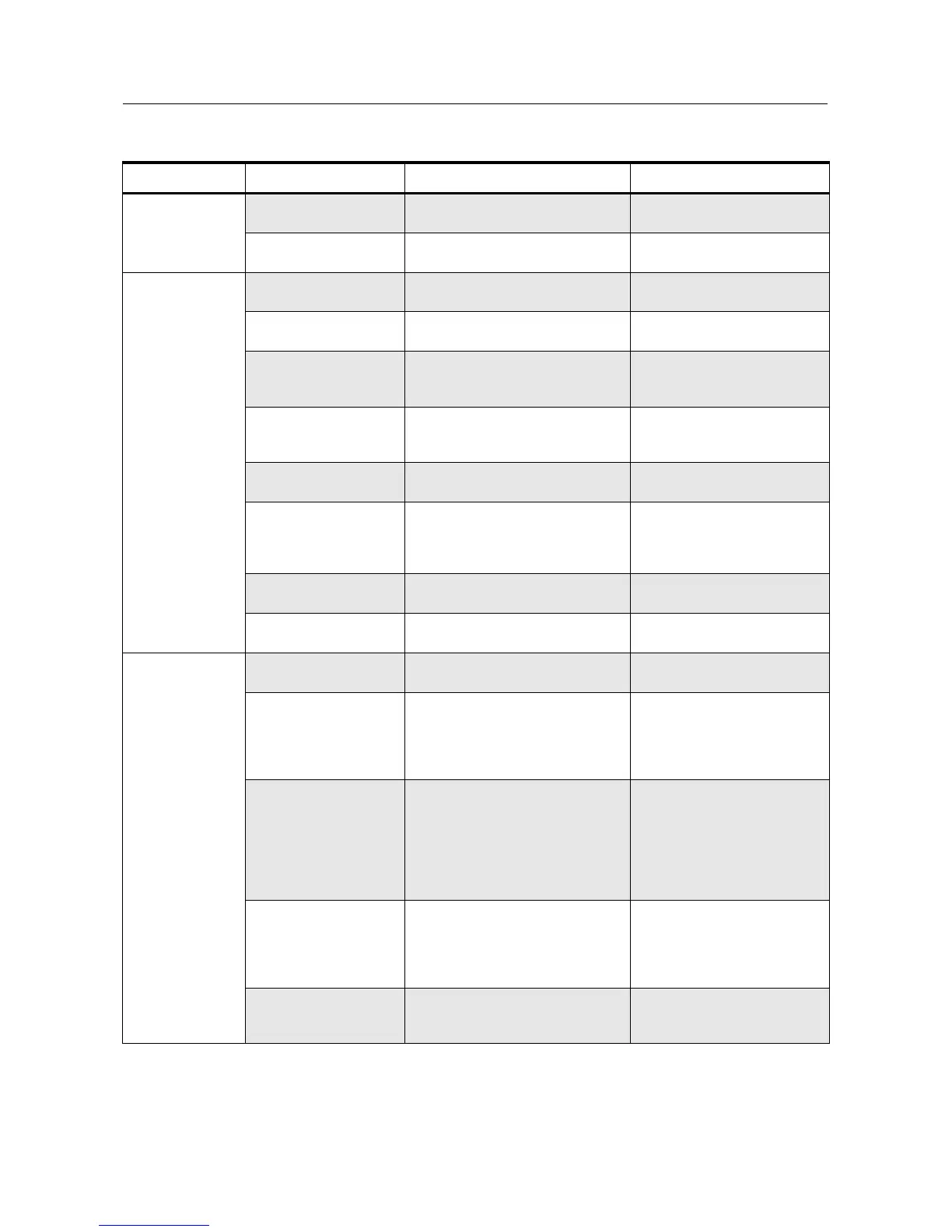
Symptom Possible Causes Procedure Corrective Action
No Transmit (no
TX LED indication)
1. PTT switch defective. Verify U401-71 goes low when PTT
is pressed.
Replace PTT switch S441.
2. EXT MIC PTT fault Verify U401-72 goes low when J471-
4 is grounded.
Check/replace Q470, L471 etc.
No Transmit (TX
LED indication OK)
1. Synthesizer out of lock Refer to Synthesiser trouble-
shooting table
.
Refer to Synthesiser trouble-
shooting table
.
2. No TX_ENABLE Verify U401-50 is high when pin 71
or 72 is low.
Check/replace U401.
3. TX DC switch fault Verify Q171-C is 0V in TX.
Verify Q170-C is at Vbatt in TX.
Replace Q171.
Check for shorts, replace Q170.
4. Power control fault Check Q150 and U150 dc voltages
per schematic and
Synthesiser
troubleshooting table
.
Repair/replace defective com-
ponents
5. No TX injection Check that RF level at jct. R100/
R101 per schematic.
Check U251, L291-292, C290-
291.
6. No 5T source Verify Q312 gate is 0V dc in TX
Verify Q312 drain is 5V dc in TX.
Check/replace Q313.
Check for shorts, check/replace
Q312.
7. TX gain stage failure Check RF levels at Q100 and U110
per schematic.
Troubleshoot Q100/U110 and
associated circuitry.
8. Antenna switch failure Verify dc voltage at jct. R122/L120 is
approx 1.5V.
Check/replace D120-121, L120-
121, R120-122, etc.
Low Power 1. Low TX injection Check that RF level at jct. R100/
R101 per schematic.
Check U251, L291-292, C290-
291.
2. Low gain in TX stage Verify dc voltage at Q100-E is ~0.5V
(UHF).
Verify that RF level at U110-1 is
approx. 1.6V (UHF).
Verify 5T voltage is correct.
Troubleshoot Q100 circuitry.
Troubleshoot Q100 circuitry.
Check/replace Q100.
3. Incorrect control volt-
age
Verify that the dc voltage at
PWR_SET (R162) is approx 1.8V dc
(at 1 watt) to 2.6V dc (at 4-5 watts).
Verify that the dc voltage at U110-2
is approx 2-3V dc (at 1 watt) to 3-4V
dc (at 4-5 watts). (See schematic.)
Check programming. Trouble-
shoot controller circuitry. Check/
replace U451.
Troubleshoot U150, Q150 and
associated circuitry.
4. Antenna switch defect Verify dc voltage at jct.R121/L120
(UHF) is approx 1.7V. Note: Do not
attempt to measure RF or DC
voltages at the diodes. Damage to
test equipment may occur.
Check/replace D120-121, L120-
121, R120-122, etc.
5. Harmonic filter defect Visually inspect components C130-
137, L130-132. Check dc continuity
of L130-132 in RX mode only.
Repair/replace if necessary.

 Loading...


