Chapter 2
TROUBLESHOOTING TABLES
1.0 Troubleshooting Tables for Board and IC Signals (includes
Controller, DC Regulation and Audio)
This section contains detailed troubleshooting tables. These tables should be used as a guide in
determining the problem areas. They are not a substitute for knowledge of circuit operation and
astute troubleshooting techniques. It is advisable to refer to the related detailed circuit descriptions
in the theory of operation sections prior to troubleshooting a radio.
Most troubleshooting tables end up by pointing to an IC to replace. It is not always noted, but it is
good practice to verify supplies and grounds to the affected IC and to trace continuity to the
malfunctioning signal and related circuitry before replacing any IC. For instance, if a clock signal is
not available at a destination, continuity from the source IC should be checked before replacing the
source IC.
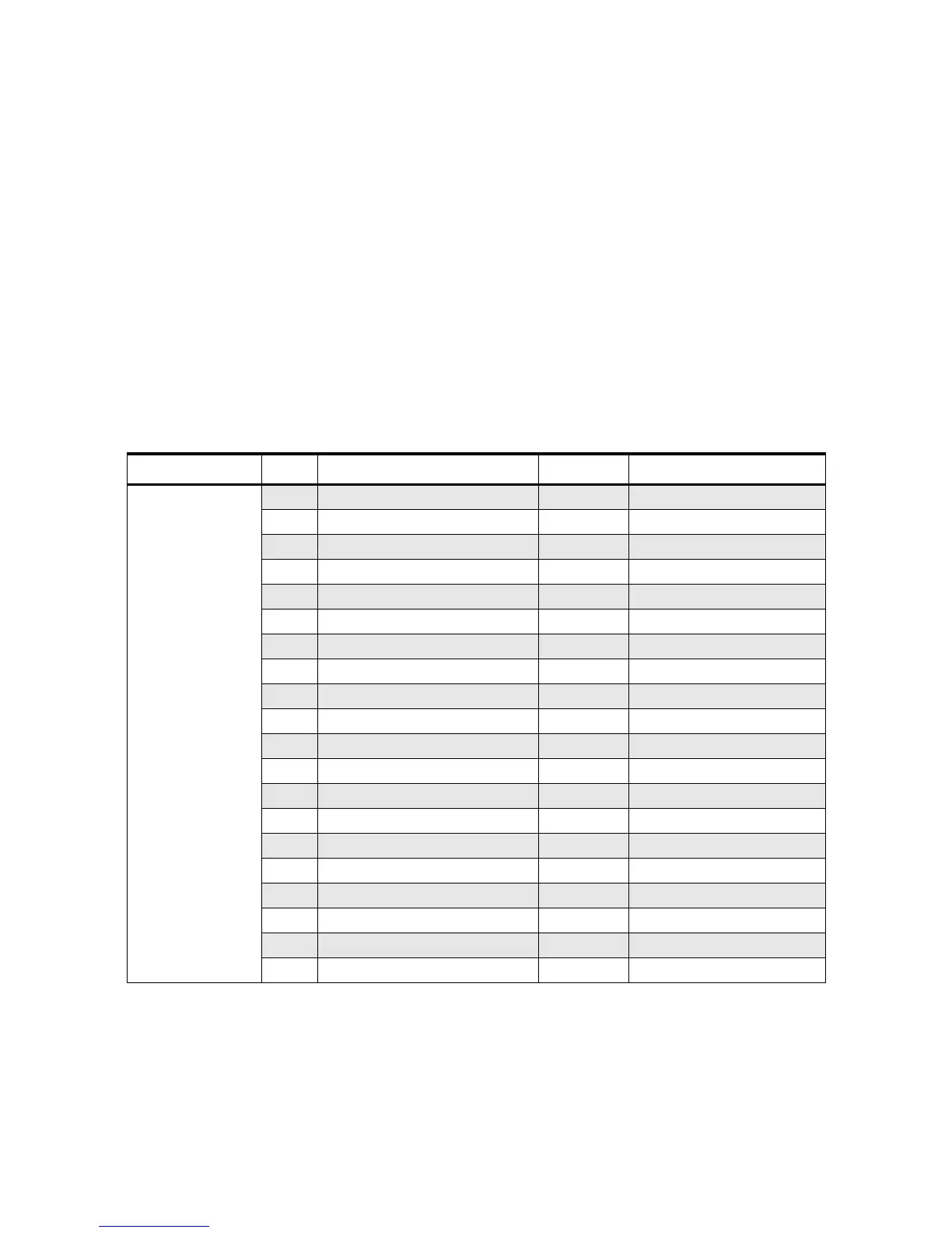
IC Designator Pin Pin Function DC Voltage Comments (Condition)
U51
IFIC
1 RF input 44.85 MHz 1.20
2 RF input decoupling 1.20
3 2nd LO osc output 4.02
4 2nd LO osc input 4.60
5 RSSI output 0.74 (no received signal)
6 Vcc 4.70
7 Audio feedback 0.89
8 Audio output 1.44 DEMOD to stage U510
9 RSSI feedback 0.74 (no received signal)
10 Quad detector input 2.22
11 Limiter output 1.25
12 Limiter decoupling 2 1.30
13 Limiter decoupling 1 1.30
14 Limiter input 1.28
15 Ground GND
16 IF amp output 1.22
17 IF amp decoupling 2 1.26
18 IF amp input 1.26
19 IF amp decoupling 1 1.26
20 2nd mixer output 3.09

 Loading...


