10
RECORDING YOUR CONNECTIONS
Switch
options
IPPV option
Telco returnA/B In RF Bypass
Dual A/B
RF Bypass
TV
R
RF
IN
CABLE IN
TO RF IN
TV Pass Card
AUX AU DIO IN
AUDI O O UT
VIDEO
SPDIF
SWITCHED
60Hz
500W MAX
105-125V
4A MA X
TO
TV/VCR
L
S-VIDEO
IR
CABLE IN
A
B
RF
OUT
RF
IN
CONV
IN
RF OUT
B
A
CABLE OUT
CABLE IN
AUDIO
IN
RLVIDEO
IN
S-VIDEO
IN
RLVIDEO
OUT
S-VIDEO
OUT
AUDIO
OUT
S-VIDEO
MONITOR
OUT
VIDEO
VIDEO 2
COAXIAL
OPTICAL
IN R
R
L
L
VS
VIDEO 1
IN
OUT R L
V
V
S
S
CABLE IN
S-VIDEO IN
S-VIDEO OUT
VIDEO IN
VIDEO OUT
LR
AUDIO
OUT
AUDIO
IN
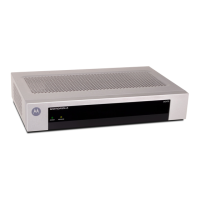
Use this diagram to record cable connections from the rear panel. Later you
can use this diagram to reconnect your system if you move the equipment,
or add new equipment.
Disconnect the power from the DCT2000 before connecting or changing cable
connections. Do not place another component or object on top of the DCT2000.
 Loading...