Chapter 1
THEORY OF OPERATION
1.0 Introduction
This Chapter provides a detailed theory of operation for the UHF circuits in the radio. Schematic
diagrams and board layout diagrams are included in Chapter 4 in this Section of the manual.
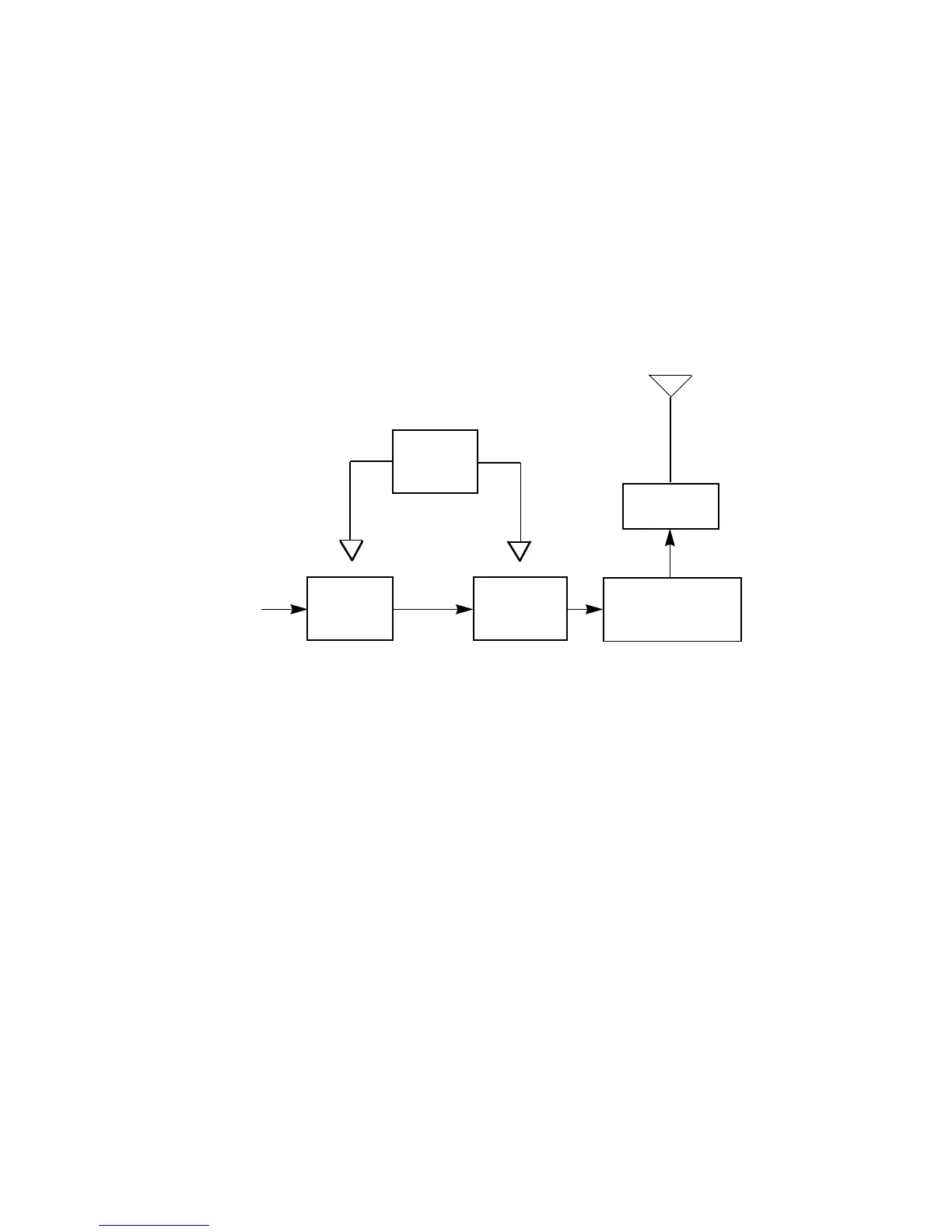
2.0 Transmitter
2.1 General
(Refer to Figure 1-1)
The UHF transmitter contains five basic circuits:
1. Power Amplifier
2. Antenna Switch
3. Harmonic Filter
4. Antenna Matching Network
5. Power Control Integrated Circuit (PCIC)
2.1.1 Power Amplifier
The power amplifier consists of two devices:
1. 9Z67 LDMOS driver IC (U101) and
2. PRF1507 LDMOS PA (Q110)
The 9Z67 LDMOS driver IC contains a 2 stage amplification with a supply voltage of 7.3V.
Figure 1-1 Transmitter Block Diagram
PCIC
Antenna
PA
Driver
Vcontrol
Vcontrol
From VCO
Jack
PA - Final
Stage
Antenna Switch/
Harmonic Filter/
Matching Network
 Loading...