Chapter 1
THEORY OF OPERATION
1.0 Overview
This section provides a detailed theory of operation for the radio and its components..
2.0 Radio Power Distribution
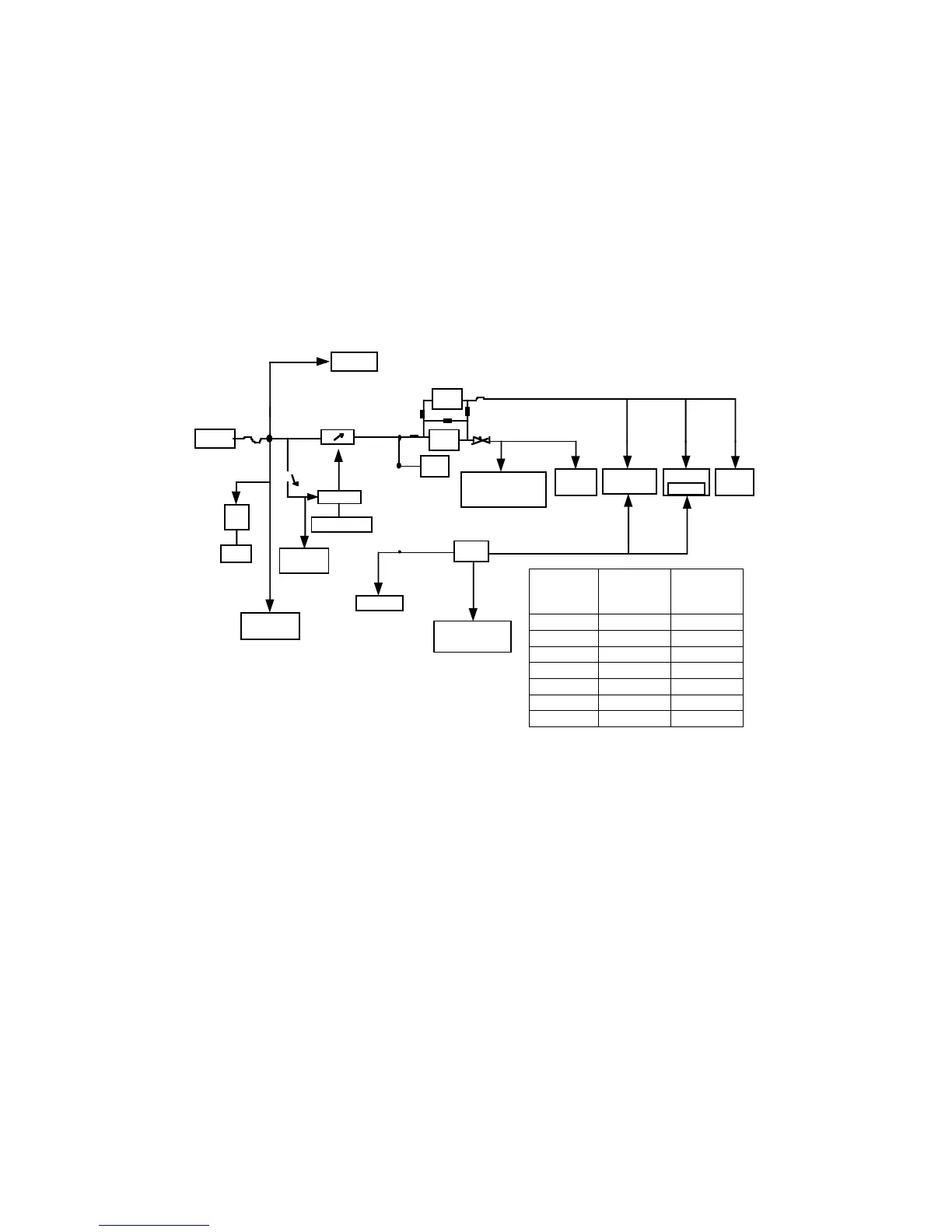
Figure 1-1 illustrates the DC distribution throughout the radio board. A 7.5V battery (BATT 7.5V)
supplies power directly to the electronic ON/OFFcontrol as UNSWB+. When the radio is turned on,
MECH_SWB+ (ON/OFF volume control) will trigger the electronic ON/OFFcontrol(momentary-on
path), then SWB+ is distributed as shown in Figure Figure 1-1. Vdda from 3.3V Vdda regulator will
then supply the microprocessor. Data is then sent to ASFIC_CMP to turn on GCB4(DAC). GCB4
will take over the momentary-on path within 12ms. SWB+ will continue to support the whole board
until the radio is turned off.
Radio will be turned-off on two conditions;
1. MECH_SWB+ turned off
2. Low battery
When low battery level is detected by the microprocessor through both conditions above, it will
store the radio personality data to EEPROM before turning off.
Figure 1-1 DC Power Distribution Block Diagram
Control
On/Off Switch
SWB+
Fuse
Low Battery
Detect
Ant. SW
PCIC(ALC)
PA, Driver
LI Ion
3.5V
Reg.
7.5V
Audio PA
Vddd
Reg.
5V
ASFIC_CMP
VCOBIC
FRACTN
LVZIF
* LCD
Driver
5V
RF. AMP, IF AMP
Ext. RX.
MECH.
SWB+
UNSWB+
TX.
Vdda
Reg.
R1
R5
R2
R3
Vdda
Vddd
Battery
Reg.
MCU Micro P, ROM
& EEPROM
Buffer (NU)
Led
Jumpers
Dual Vdd
Regulator
Scheme
Single Vdd
Regulator
Scheme
R1 Y Y
R2 N N
R3 N Y
R4 N N
R5 Y N
Vdda Y N
SW. Reg. N N
*Not applicable to GP344/GP644
 Loading...