Maintenance: 800 MHz Troubleshooting Charts 8-45
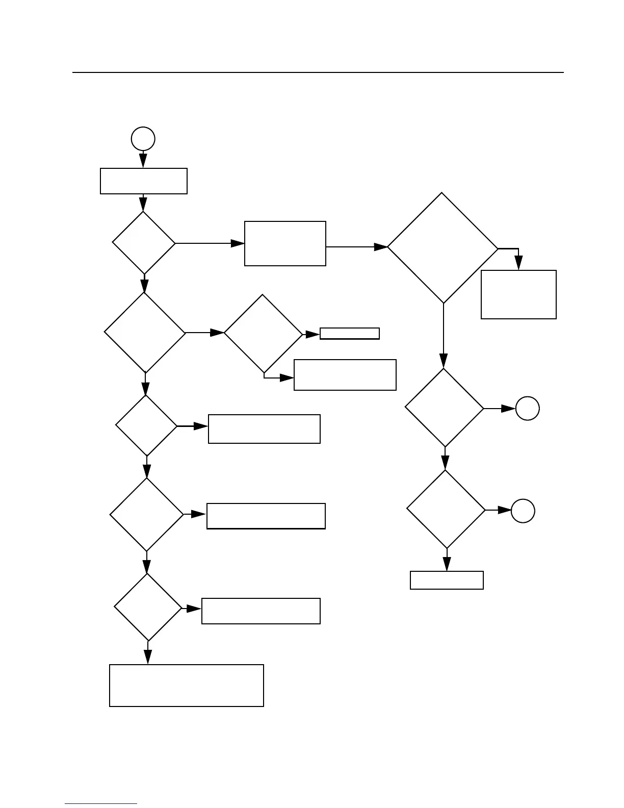
8.14.5 Troubleshooting Flow Chart for Receiver (for PCB No. 8471827L03)
(Sheet 2 of 2)
IF Signal at
L303?
No
RF Signal at
pin 8 of U301?
RF Signal at
C316?
No
Check RF amp Q302 Stage
Inject RF into J101
Check filter FL301 and
associated circuitry
Check U301, C321, R311
and R320.
Yes
1st LO O/P
OK?
Locked?
Yes
Check FGU
Yes
Trace IF signal from
L303 to Q350.
Check for bad XTAL
filter.
No
Yes
Q350 collector
OK?
IF signal present?
Before replacing
U350, check U350
voltages; trace IF
signal path.
Yes
Check for 3.0VDC
@ Q350-C
Is 5V supply
present?
Check U247.
No
No
No
Yes
Yes
A
B
RF Signal at
C302?
No
Yes
Check harmonic filter L101 & L102 and
antenna switch CR101, CR102, L103
and associated components.
No or
weak RF
Check filter FL300 &
associated circuitry.
Yes
A
RF Signal at
C301?
 Loading...


