Home
Motorola
Two-Way Radio
HT Series
Motorola HT Series User Manual
5
of 1
of 1 rating
639 pages
Give review
Manual
Specs
To Next Page
To Next Page
To Previous Page
To Previous Page
Loading...
9-386
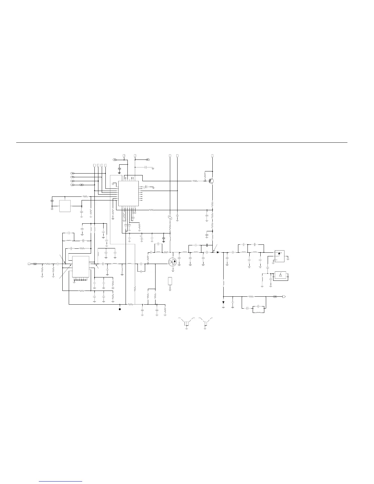
VHF Circuit Board/Schematic Diagrams and Parts List
C3535
5185963A15
1
MICROSTRIP
LM50C
27pF
15pF
120pF
C3536
C3523
18pF
C3524
TAB3
4
TAB4
3300pF
C3568
J3502
ANTENNA_NUT
1
TAB1
2
TAB2
3
12
3
SHIELD
SH3501
SHIELD
RX_IN
5V
1
2
TP3502
UNSWB+
SHIELD
SH3502
SHIELD
Q3561
D
G
S
DATA
Q3501
330K
220pF
C3564
R3564
0.1
R3519
R3547
RX_IN_1_PA
12K
CSX
RESET
C3546
330pF
330pF
C3509
C3506
.022uF
68nH
7.66nH
L3504
L3513
47pF
C3512
100
R3544
UNSW_LPLUS_3_PA
UNSWB_LPLUS_2_PA
D3551
RESET_1_PA
33pF
330pF
C3503
C3501
300
R3503
R3501
18
300
R3502
16
RFIN
11
G2
6
RFOUT1
RFOUT2
7
1
VCNTRL
NC3
10
NC4
15
GND1
4
GND2
5
GND3
12
GND4
13
2
VG1
3
VG2
U3501
NC1
8
NC2
9
5V_2_PA
UNSWB+
16
V45
15
VG
6
VL
19
VLIM
17
VSH
DATA_2_PA
23
RX
32
T1
2
T2
30
TEMP
V1
20
14
V10
V2
18
V3
24
GND1
8
GND2
25
4
INT
OVI
31
11
Q
QX
10
1
RF
21
RS
CI
3
5
CJ
7
CL
26
CLK
12
CQ
CQX
13
28
DATA
9
F168
U3502
22
ANO
BPOS
27
29
CEX
BEAD
L3519
BEAD
CLK_2_PA
CSX_2_PA
CLK
UNSWB+
UNSWB+
R3562
C3550
7.5pF
33K
100
11.03nH
R3545
L3512
C3534
4.7pF
C3533
7.5pF
R3546
33K
C3532
68pF
330pF
R3512
C3518
120
.022uF
C3504
1uH
L3523
C3526
C3525
.022uF
L3503
10pF
68nH
12K
R3561
.022uF
C3565
3300pF
3300pF
C3562
C3563
R3563
270K
C3561
.022uF
C3527
1.5pF
L3521
7.66nH
C3514
470pF
C3515
220pF
3300pF
C3521
C3569
.022uF
5.6K
R3571
R3569
R3572
120
120
R3573
120
7.66nH
56pF
L3552
C3551
C3552
39
68pF
R3551
R3570
100pF
10K
C3516
1uF
C3517
L3551
43.67nH
L3532
43.67nH
43.67nH
L3531
23.75nH
L3522
C3505
33pF
R3505
5.6pF
330
C3539
1uF
C3519
22pF
C3560
30.54nH
L3518
39nH
L3538
L3515
13.85nH
18nH
L3511
C3544
R3542
330pF
5.6K
C3547
.022uF
R3541
NU
6.8K
R3543
100
C3531
18pF
C3537
20pF
HEATSINK
3
H3501
RF_JACK
J3501
GND
4
1
2
.022uF
C3543
330pF
C3541
C3542
30pF
.022uF
C3513
C3502
33pF
T
X_INJ
5.6nH
L3501
GND
3
POS
VOUT
2
U3503
D3521
TX_INJ_1_PA
C3528
9.1pF
7.5k
R3548
330pF
C3507
C3506
.022uF
68nH
L3502
VD1
14
ZWG0130021-D
NU
NU
NU
C3566
100pF
R3565
330K
NU
100
R3513
C3570
330pF
0
NU
R3566
470pF
C3571
C3567
330pF
1.55VDC if VTP 3502 = 4.1VDC
1.44VDC if VTP 3502 = 3.8VDC
2V - 5V
RMS
> 200mV RMS
300 ~ 500mV RMS
Tx: 1.6VDC
Tx: 0.8VDC
3VDC for 5.5W
2.8VDC for 1W
4.0 - 4.2VDC for 5.5W
3.9 - 4.1VDC for 3W
3.7 - 4.0VDC for 1W
Figure 9-237. VHF (136-174 MHz) T
ransmitter Schematic Dia
gram
535
537
Table of Contents
Default Chapter
2
Computer Software Copyrights
2
Disclaimer
2
Document Copyrights
2
Foreword
2
Product Safety and Rf Exposure Compliance
2
Trademarks
2
Document History
3
Table of Contents
5
List of Figures
9
Related Publications
19
FMRC Approved Equipment
21
Intrinsically Safe Radio Information
21
Repair of FMRC Approved Products
22
Do Not Substitute Options or Accessories
23
Chapter 1 Introduction
25
Scope of Manual
25
Warranty and Service Support
25
Piece Parts
26
Technical Support
26
Further Assistance from Motorola
26
Radio Model Chart and Specification
27
Radio Model Information
27
Chapter 2 Radio Power Distribution
29
Figure 2-1. DC Power Distribution Block Diagram
29
Chapter 3 Keypad
31
Figure 3-1. Keypad Block Diagram
31
Controller Board
32
Figure 3-2. Controller Block Diagram
32
Figure 3-3. RTC Circuit
33
Chapter 4 UHF Band 1 Theory of Operation
35
Transmitter
35
Figure 4-1. Transmitter Block Diagram
35
Antenna Matching Network
36
Antenna Switch
36
Harmonic Filter
36
Receiver
37
Figure 4-2. UHF Receiver Block Diagram
37
Frequency Generation Circuitry
38
Figure 4-3. Frequency Generation Unit Block Diagram
38
Synthesizer
39
Figure 4-4. Synthesizer Block Diagram
39
Voltage-Controlled Oscillator (VCO)
40
Figure 4-5. VCO Block Diagram
40
Chapter 5 UHF Band 2 Theory of Operation
43
Transmitter
43
Figure 5-1. Transmitter Block Diagram
43
Receiver
45
Figure 5-2. UHF Receiver Block Diagram
45
Frequency Generation Circuitry
46
Figure 5-3. Frequency Generation Unit Block Diagram
46
Synthesizer
47
Figure 5-4. Synthesizer Block Diagram
47
Voltage-Controlled Oscillator (VCO)
48
Figure 5-5. VCO Block Diagram
48
Chapter 6 VHF Theory of Operation
51
Transmitter
51
Figure 6-1. Transmitter Block Diagram
51
Receiver (for All Models Except those with PCB 8486473Z04)
53
Figure 6-2. VHF Receiver Block Diagram
53
Receiver (for Models with PCB 8486473Z04)
55
Figure 6-3. VHF Receiver Block Diagram
55
Frequency Generation Circuitry
58
Figure 6-4. Frequency Generation Unit Block Diagram
58
Synthesizer
59
Figure 6-5. Synthesizer Block Diagram
59
Voltage-Controlled Oscillator (VCO)
60
Figure 6-6. VCO Block Diagram
60
Chapter 7 Low Band, 800 Mhz, Passport & 900 Mhz Theory of Operation
63
Introduction
63
Low Band Transmitter
63
Figure 7-1. Low Band Transmitter Block Diagram
63
Low Band Receiver
65
Figure 7-2. Low Band Receiver Block Diagram
65
Synthesizer
67
Figure 7-3. Low Band Frequency Generation Unit Block Diagram
67
Voltage Control Oscillators (VCO)
68
Figure 7-4. Low Band Synthesizer Block Diagram
68
800 Mhz Transmitter
69
Figure 7-5. 800 Mhz Transmitter Block Diagram
69
800 Mhz Receiver
71
Synthesizer
74
Figure 7-8. 800 Mhz Frequency Generation Unit Block Diagram
74
Figure 7-9. 800 Mhz Synthesizer Block Diagram
75
Figure 7-10. 800 Mhz VCO Block Diagram
76
Trunked Radio Systems
77
Power Supplies
78
7.10 900 Mhz Transmitter
79
Figure 7-11. Transmitter Block Diagram
79
Power Amplifier
80
7.11 900 Mhz Receiver
81
Figure 7-12. 900 Mhz Receiver Block Diagram (for PCB No. 8485910Z01)
81
Figure 7-13. 900 Mhz Receiver Block Diagram (for PCB No. 8471203M01)
82
7.12 Frequency Generation Circuitry
86
7.13 900 Mhz Synthesizer
86
Figure 7-14. Frequency Generation Unit Block Diagram
86
Figure 7-15. Synthesizer Block Diagram
87
900 Mhz Voltage Control Oscillator (VCO)
88
Figure 7-16. VCO Block Diagram
88
Chapter 8 Maintenance
91
Introduction
91
Preventive Maintenance
91
Inspection
91
Safe Handling of CMOS and LDMOS
92
General Repair Procedures and Techniques
92
Recommended Test Tools
94
Replacing the Circuit Board Fuse
95
Figure 8-1. Uhf/Vhf/Low Band/800 Mhz/900 Mhz Circuit Board Fuse Locations
95
Removing and Reinstalling the Circuit Board
96
Figure 8-2. Circuit Board Removal and Reinstallation
96
Power up Self-Test Error Codes
97
8.10 UHF Band 1 Troubleshooting Charts
98
Troubleshooting Flow Chart for Transmitter
104
Troubleshooting Flow Chart for Synthesizer
105
Troubleshooting Flow Chart for Vco
106
8.11 UHF Band 2 Troubleshooting Charts
107
8.12 VHF Troubleshooting Charts
116
8.13 Low Band Troubleshooting Charts
125
8.14 800 Mhz Troubleshooting Charts
131
8.15 Passport Trunking Troubleshooting Chart
140
8.16 Keypad Troubleshooting Chart
141
8.17 900 Mhz Troubleshooting Charts
142
Chapter 9 Schematic Diagrams, Overlays, and Parts Lists
151
Introduction
151
Flex Layout
152
Figure 9-1. Keypad-Controller Interconnect Flex
153
Figure 9-2. Keypad-Controller Interconnect Flex Schematic Diagram
153
Figure 9-3. Universal Flex Connector
154
Figure 9-4. Universal Flex Connector Schematic Diagram
155
Keypad Top and Bottom Overlays
156
Figure 9-5. Keypad Top and Bottom Board Overlays
156
Keypad Circuit Board/Schematic Diagrams and Parts List
157
Figure 9-6. Keypad Board (5000 and 7000 Series) Schematic Diagram
157
Figure 9-7. 9000 Series Keypad Top and Bottom Board Overlays
159
Figure 9-8. 9000 Series Keypad Board Schematic Diagram
160
Controller Circuit Board/Schematic Diagrams and Parts List
163
Figure 9-9. VHF/UHF Complete Controller Schematic Diagram
163
Figure 9-10. VHF/UHF Controller ASFIC/ON_OFF Schematic Diagram
164
Figure 9-11. VHF/UHF Controller ASFIC/ON_OFF Schematic Diagram
165
Figure 9-12. VHF/UHF Controller Microprocessor Schematic Diagram
166
Figure 9-13. VHF/UHF Controller Microprocessor Schematic Diagram
167
Figure 9-14. Controller Memory Schematic Diagram
168
Figure 9-15. Controller Audio Power Amplifier Schematic Diagram
169
Figure 9-16. Controller Interface Schematic Diagram
170
UHF Band 1 Circuit Board/Schematic Diagrams and Parts List (PCB 8480450Z03)
171
Figure 9-17. UHF (403-470 Mhz) 5000/7000 Series Main Board Top Side
171
Figure 9-18. UHF (403-470 Mhz) 5000/7000 Series Main Board Bottom Side
172
Figure 9-19. UHF (403-470 Mhz) Controls and Switches Schematic Diagram
173
Figure 9-20. UHF (403-470 Mhz) Receiver Front End Schematic Diagram
174
Figure 9-21. UHF (403-470 Mhz) Receiver Back End Schematic Diagram
175
Figure 9-22. UHF (403-470 Mhz) Synthesizer Schematic Diagram
176
Figure 9-23. UHF (403-470 Mhz) Voltage Controlled Oscillator Schematic Diagram
177
Figure 9-24. UHF (403-470 Mhz) Transmitter Schematic Diagram
178
UHF Band 1 Circuit Board/Schematic Diagrams and Parts List (PCB 8480450Z13 / 8480587Z05)
183
Figure 9-25. UHF (403-470 Mhz) 5000/7000 Series Main Board Top Side
183
Figure 9-26. UHF (403-470 Mhz) 5000/7000 Series Main Board Bottom Side
184
Figure 9-27. UHF (403-470 Mhz) 5000/7000 Series Main Board Top Side
185
Figure 9-28. UHF (403-470 Mhz) 5000/7000 Series Main Board Bottom Side
186
Figure 9-29. UHF (403-470 Mhz) Controls and Switches Schematic Diagram
187
Figure 9-30. UHF (403-470 Mhz) Receiver Front End Schematic Diagram
188
Figure 9-31. UHF (403-470 Mhz) Receiver Back End Schematic Diagram
189
Figure 9-32. UHF (403-470 Mhz) Synthesizer Schematic Diagram
190
Figure 9-33. UHF (403-470 Mhz) Voltage Controlled Oscillator Schematic Diagram
191
Figure 9-34. UHF (403-470 Mhz) Transmitter Schematic Diagram
192
UHF Band 1 Circuit Board/Schematic Diagrams and Parts List (PCB 8480450Z14)
197
Figure 9-35. UHF (403-470 Mhz) 5000/7000 Series Main Board Top Side PCB No. 8480450Z14
197
Figure 9-36. UHF (403-470 Mhz) 5000/7000 Series Main Board Bottom Side PCB No. 8480450Z14
198
Figure 9-37. UHF (403-470 Mhz) Controls and Switches Schematic Diagram
199
Figure 9-38. UHF (403-470 Mhz) Receiver Front End Schematic Diagram
200
Figure 9-39. UHF (403-470 Mhz) Receiver Back End Schematic Diagram
201
Figure 9-40. UHF (403-470 Mhz) Synthesizer Schematic Diagram
202
Figure 9-41. UHF (403-470 Mhz) Voltage Controlled Oscillator Schematic Diagram
203
Figure 9-42. UHF (403-470 Mhz) Harmonic Filter Schematic Diagram
204
Figure 9-43. UHF (403-470 Mhz) Transmitter Schematic Diagram
205
Figure 9-44. UHF (403-470 Mhz) Complete Controller Schematic Diagram
206
Figure 9-45. UHF (403-470 Mhz) Controller ASFIC/ON_OFF Schematic Diagram
207
Figure 9-46. UHF (403-470 Mhz) Controller Microprocessor Schematic Diagram
208
Figure 9-47. UHF (403-430 Mhz) Controller Memory Schematic Diagram
209
Figure 9-48. UHF (403-470 Mhz) Controller Audio Power Amplifier Schematic
210
Figure 9-49. UHF (403-470 Mhz) Controller Interface Schematic Diagram
211
UHF Band 1 Circuit Board/Schematic Diagrams and Parts List (PCB 8486458Z02)
217
Figure 9-50. UHF (403-470 Mhz) 5000/7000 Series Main Board Top Side PCB No. 8486458Z02
217
Figure 9-51. UHF (403-470 Mhz) 5000/7000 Series Main Board Bottom Side PCB No. 8486458Z02
218
Figure 9-52. UHF (403-470 Mhz) Controls and Switches Schematic Diagram
219
Figure 9-53. UHF (403-470 Mhz) Receiver Front-End Schematic Diagram
220
Figure 9-54. UHF (403-470 Mhz) Receiver Back-End Schematic Diagram
221
Figure 9-55. UHF (403-470 Mhz) Synthesizer Schematic Diagram
222
Figure 9-56. UHF (403-470 Mhz) Voltage Controlled Oscillator Schematic Diagram
223
Figure 9-57. UHF (403-470 Mhz) Harmonic Filter Schematic Diagram
224
Figure 9-58. UHF (403-470 Mhz) Transmitter Schematic Diagram
225
Figure 9-59. UHF (403-470 Mhz) Controller ASFIC/ON_OFF Schematic Diagram
226
UHF Band 1 Circuit Board/Schematic Diagrams and Parts List (PCB 8486458Z03)
231
Figure 9-60. UHF (403-470 Mhz) 5000/7000 Series Main Board Top Side PCB No. 8486458Z03
231
Figure 9-61. UHF (403-470 Mhz) 5000/7000 Series Main Board Bottom Side PCB No. 8486458Z03
232
Figure 9-62. UHF (403-470 Mhz) Controls and Switches Schematic Diagram
233
Figure 9-63. UHF (403-470 Mhz) Receiver Front End Schematic Diagram
234
Figure 9-64. UHF (403-470 Mhz) Receiver Back End Schematic Diagram
235
Figure 9-65. UHF (403-470 Mhz) Synthesizer Schematic Diagram
236
Figure 9-66. UHF (403-470 Mhz) Voltage Controlled Oscillator Schematic Diagram
237
Figure 9-67. UHF (403-470 Mhz) Harmonic Filter Schematic Diagram
238
Figure 9-68. UHF (403-470 Mhz) Transmitter Schematic Diagram
239
Figure 9-69. UHF (403-470 Mhz) Complete Controller Schematic Diagram
240
Figure 9-70. UHF (403-470 Mhz) Controller ASFIC/ON_OFF Schematic Diagram
241
Figure 9-71. UHF (403-470 Mhz) Controller Microprocessor Schematic Diagram
242
Figure 9-72. UHF (403-430 Mhz) Controller Memory Schematic Diagram
243
Figure 9-73. UHF (403-470 Mhz) Controller Audio Power Amplifier Schematic
244
Figure 9-74. UHF (403-470 Mhz) Controller Interface Schematic Diagram
245
UHF Band 1 Circuit Board/Schematic Diagrams and Parts List (PCB 8415234H01, 8415234H02, 8415234H05, 8415234H08)
251
Figure 9-75. UHF (403-470 Mhz) Main Board Top Side PCB No. 8415234H01
251
Figure 9-76. UHF (403-470 Mhz) Main Board Bottom Side PCB No. 8415234H01
252
Figure 9-77. UHF (403-470 Mhz) Main Board Top Side PCB No. 8415234H02
253
Figure 9-78. UHF (403-470 Mhz) Main Board Bottom Side PCB No. 8415234H02
254
Figure 9-79. UHF (403-470 Mhz) Main Board Top Side PCB No. 8415234H05
255
Figure 9-80. UHF (403-470 Mhz) Main Board Bottom Side PCB No. 8415234H05
256
Figure 9-81. UHF (403-470 Mhz) Main Board Top Side PCB No. 8415234H08
257
Figure 9-82. UHF (403-470 Mhz) Main Board Bottom Side PCB No. 8415234H08
258
Figure 9-83. UHF Controls and Switches Schematic Diagram for (403-470Mhz for 8415234H01)
259
Figure 9-84. UHF Controls and Switches Schematic Diagram for
260
Figure 9-85. UHF Controls and Switches Schematic Diagram for
261
Figure 9-86. UHF Controls and Switches Schematic Diagram for (403-470Mhz for 8415234H08)
262
Figure 9-87. UHF Receiver Front End Schematic Diagram for
263
Figure 9-88. UHF Receiver Front End Schematic Diagram for
264
Figure 9-89. UHF Receiver Front End Schematic Diagram for
265
Figure 9-90. UHF Receiver Front End Schematic Diagram for
266
Figure 9-91. UHF Receiver Back End Schematic Diagram for (403-470Mhz for 8415234H01)
267
Figure 9-92. UHF Receiver Back End Schematic Diagram for
268
Figure 9-93. UHF Receiver Back End Schematic Diagram for (403-470Mhz for 8415234H05)
269
Figure 9-94. UHF Receiver Back End Schematic Diagram for (403-470Mhz for 8415234H08)
270
Figure 9-95. UHF Synthesizer Schematic Diagram
271
Figure 9-96. UHF Voltage Controlled Oscillator Schematic Diagram
272
Figure 9-97. UHF Harmonic Filter Schematic Diagram for
273
Figure 9-98. UHF Harmonic Filter Schematic Diagram for
274
Figure 9-99. UHF Harmonic Filter Schematic Diagram for
275
Figure 9-100.UHF Harmonic Filter Schematic Diagram for
276
Figure 9-101.UHF Transmitter Schematic Diagram for
277
Figure 9-102.UHF Transmitter Schematic Diagram for
278
Figure 9-103.UHF Transmitter Schematic Diagram for
279
Figure 9-104.UHF Transmitter Schematic Diagram for
280
Figure 9-105.Complete Controller Schematic Diagram for (403-470Mhz for 8415234H01, 8415234H05, 8415234H08)
281
Figure 9-106.Controller ASFIC/ON_OFF Schematic Diagram for (403-470Mhz for 8415234H01, 8415234H05, 8415234H08)
282
Figure 9-107.Controller Microprocessor Schematic Diagram for (403-470Mhz for 8415234H01, 8415234H05, 8415234H08)
283
Figure 9-108.Controller Memory Schematic Diagram for (403-470Mhz for 8415234H01, 8415234H05, 8415234H08)
284
Figure 9-109.Controller Audio Power Amplifier Schematic Diagram for
285
Figure 9-110.Controller Interface Schematic Diagram for (403-470Mhz for 8415234H01, 8415234H05, 8415234H08)
286
9.12 UHF Band 1 Circuit Board/Schematic Diagrams and Parts List
313
Figure 9-90. UHF (403-470 Mhz) 9000 Series Main Board Top Side PCB
313
Figure 9-91. UHF (403-470 Mhz) 9000 Series Main Board Bottom Side PCB
314
Figure 9-92. UHF (403-470 Mhz) Controls and Switches Schematic Diagram
315
Figure 9-93. UHF (403-470 Mhz) Receiver Front End Schematic Diagram
316
Figure 9-94. UHF (403-470 Mhz) Receiver Back End Schematic Diagram
317
Figure 9-95. UHF (403-470 Mhz) Synthesizer Schematic Diagram
318
Figure 9-96. UHF (403-470 Mhz) Voltage Controlled Oscillator Schematic Diagram
319
Figure 9-97. UHF (403-470 Mhz) Transmitter Schematic Diagram
320
UHF Band 2 Circuit Board/Schematic Diagrams and Parts List (PCB 8485641Z02)9-175
325
Figure 9-98. UHF (450-527 Mhz) 5000/7000 Series Main Board Top Side
325
Figure 9-99. UHF (450-527 Mhz) 5000/7000 Series Main Board Bottom Side
326
Figure 9-100.UHF (450-527 Mhz) Controls and Switches Schematic Diagram
327
Figure 9-101.UHF (450-527 Mhz) Receiver Front End Schematic Diagram
328
Figure 9-102.UHF (450-527 Mhz) Receiver Back End Schematic Diagram
329
Figure 9-103.UHF (450-527 Mhz) Synthesizer Schematic Diagram
330
Figure 9-104.UHF (450-527 Mhz) Voltage Controlled Oscillator Schematic Diagram
331
Figure 9-105.UHF (450-527 Mhz) Transmitter Schematic Diagram
332
UHF Band 2 Circuit Board/Schematic Diagrams and Parts List (PCB 8485641Z06 / 8485677Z03)
337
Figure 9-106.UHF (450-527 Mhz) 5000/7000 Series Main Board Top Side
337
Figure 9-107.UHF (450-527 Mhz) 5000/7000 Series Main Board Bottom Side
338
Figure 9-108.UHF (450-527 Mhz) 5000/7000 Series Main Board Top Side
339
Figure 9-109.UHF (450-527 Mhz) 5000/7000 Series Main Board Bottom Side
340
Figure 9-110.UHF (450-527 Mhz) Controls and Switches Schematic Diagram
341
Figure 9-111.UHF (450-527 Mhz) Receiver Front End Schematic Diagram
342
Figure 9-112.UHF (450-527 Mhz) Receiver Back End Schematic Diagram
343
Figure 9-113.UHF (450-527 Mhz) Synthesizer Schematic Diagram
344
Figure 9-114.UHF (450-527 Mhz) Voltage Controlled Oscillator Schematic Diagram
345
Figure 9-115.UHF (450-527 Mhz) Transmitter Schematic Diagram
346
Figure 9-116.UHF (450-527 Mhz) 5000/7000 Series Main Board Top Side
351
Figure 9-117.UHF (450-527 Mhz) 5000/7000 Series Main Board Bottom Side PCB No. 8486686Z01
352
Figure 9-118.UHF (450-527 Mhz) Controls and Switches Schematic Diagram
353
Figure 9-119.UHF (450-527 Mhz) Receiver Front End Schematic Diagram
354
Figure 9-120.UHF (450-527 Mhz) Receiver Back End Schematic Diagram
355
Figure 9-121.UHF (450-527 Mhz) Synthesizer Schematic Diagram
356
Figure 9-122.UHF (450-527 Mhz) Voltage Controlled Oscillator Schematic Diagram
357
Figure 9-123.UHF (450-527 Mhz) Harmonic Filter Schematic Diagram
358
Figure 9-124.UHF (450-527 Mhz) Transmitter Schematic Diagram
359
Figure 9-125.UHF (450-527 Mhz) Controller ASFIC/ON_OFF Schematic Diagram
360
Figure 9-126.UHF (450-527 Mhz) 5000/7000 Series Main Board Top Side
365
Figure 9-127.UHF (450-527 Mhz) 5000/7000 Series Main Board Bottom Side PCB No. 8486686Z02
366
Figure 9-128.UHF (450-527 Mhz) Controls and Switches Schematic Diagram
367
Figure 9-129.UHF (450-527 Mhz) Receiver Front End Schematic Diagram
368
Figure 9-130.UHF (450-527 Mhz) Receiver Back End Schematic Diagram
369
Figure 9-131.UHF (450-527 Mhz) Synthesizer Schematic Diagram
370
Figure 9-132.UHF (450-527 Mhz) Voltage Controlled Oscillator Schematic Diagram
371
Figure 9-133.UHF (450-527 Mhz) Harmonic Filter Schematic Diagram
372
Figure 9-134.UHF (450-527 Mhz) Transmitter Schematic Diagram
373
Figure 9-135.UHF (450-527 Mhz) Complete Controller Schematic Diagram
374
Figure 9-136.UHF (450-527 Mhz) Controller ASFIC/ON_OFF Schematic Diagram
375
Figure 9-137.UHF (450-527 Mhz) Controller Microprocessor Schematic Diagram
376
Figure 9-138.UHF (450-527 Mhz) Controller Memory Schematic Diagram
377
Figure 9-139.UHF (450-527 Mhz) Controller Audio Power Amplifier Schematic
378
Figure 9-140.UHF (450-527 Mhz) Controller Interface Schematic Diagram
379
UHF Band 2 Circuit Board/Schematic Diagrams and Parts List (PCB 8486686Z02)9-215
381
UHF Band 2 Circuit Board/Schematic Diagrams and Parts List (PCB 8415235H01, 8415235H05)
385
Figure 9-141.UHF Band 2 (450-527 Mhz) Main Board Top Side
385
Figure 9-142.UHF Band 2 (450-527 Mhz) Main Board Bottom Side
386
Figure 9-143.UHF Band 2 (450-527 Mhz) Main Board Top Side
387
Figure 9-144.UHF Band 2 (450-527 Mhz) Main Board Bottom Side
388
Figure 9-145.UHF Band 2 Controls and Switches Schematic Diagram
389
Figure 9-146.UHF Band 2 Controls and Switches Schematic Diagram
390
Figure 9-147.UHF Band 2 Receiver Front End Schematic Diagram
391
Figure 9-148.UHF Band 2 Receiver Front End Schematic Diagram
392
Figure 9-149.UHF Band 2 Receiver Back End Schematic Diagram
393
Figure 9-150.UHF Band 2 Receiver Back End Schematic Diagram
394
Figure 9-151.UHF Band 2 Synthesizer Schematic Diagram
395
Figure 9-152.UHF Band 2 Voltage Controlled Oscillator Schematic Diagram
396
Figure 9-153.UHF Band 2 Harmonic Filter Schematic Diagram
397
Figure 9-154.UHF Band 2 Harmonic Filter Schematic Diagram
398
Figure 9-155.UHF Band 2 Transmitter Schematic Diagram
399
Figure 9-156.UHF Band 2 Transmitter Schematic Diagram
400
Figure 9-157.Complete Controller Schematic Diagram
401
Figure 9-158.Controller ASFIC/ON_OFF Schematic Diagram
402
Figure 9-159.Controller Microprocessor Schematic Diagram
403
Figure 9-160.Controller Memory Schematic Diagram
404
Figure 9-161.Controller Audio Power Amplifier Schematic Diagram
405
Figure 9-162.Controller Interface Schematic Diagram
406
9.18 UHF Band 2 Circuit Board/Schematic Diagrams and Parts List
421
Figure 9-156.UHF (450-527 Mhz) 9000 Series Main Board Top Side PCB
421
Figure 9-157.UHF (450-527 Mhz) 9000 Series Main Board Bottom Side PCB
422
Figure 9-158.UHF (450-527 Mhz) Controls and Switches Schematic Diagram
423
Figure 9-159.UHF (450-527 Mhz) Receiver Front End Schematic Diagram
424
Figure 9-160.UHF (450-527 Mhz) Receiver Back End Schematic Diagram
425
Figure 9-161.UHF (450-527 Mhz) Synthesizer Schematic Diagram
426
Figure 9-162.UHF (450-527 Mhz) Voltage Controlled Oscillator Schematic Diagram
427
Figure 9-163.UHF (450-527 Mhz) Transmitter Schematic Diagram
428
Figure 9-164.UHF (450-527 Mhz) Voice Storage Schematic Diagram
429
VHF Circuit Board/Schematic Diagrams and Parts List (PCB 8486062B09)
433
Figure 9-165.VHF (136-174 Mhz) 5000/7000 Series Main Board Top Side
433
Figure 9-166.VHF (136-174 Mhz) 5000/7000 Series Main Board Bottom Side
434
Figure 9-167.VHF (136-174 Mhz) Controls and Switches Schematic Diagram
435
Figure 9-168.VHF (136-174 Mhz) Receiver Front End Schematic Diagram
436
Figure 9-169.VHF (136-174 Mhz) Receiver Back End Schematic Diagram
437
Figure 9-170.VHF (136-174 Mhz) Synthesizer Schematic Diagram
438
Figure 9-171.VHF (136-174 Mhz) Voltage Controlled Oscillator Schematic Diagram
439
Figure 9-172.VHF (136-174 Mhz) Transmitter Schematic Diagram
440
VHF Circuit Board/Schematic Diagrams and Parts List (PCB 8486062B12)
445
Figure 9-173.VHF (136-174 Mhz) 5000/7000 Series Main Board Top Side
445
Figure 9-174.VHF (136-174 Mhz) 5000/7000 Series Main Board Bottom Side
446
Figure 9-175.VHF (136-174 Mhz) Controls and Switches Schematic Diagram
447
Figure 9-176.VHF (136-174 Mhz) Receiver Front End Schematic Diagram
448
Figure 9-177.VHF (136-174 Mhz) Receiver Back End Schematic Diagram
449
Figure 9-178.VHF (136-174 Mhz) Synthesizer Schematic Diagram
450
Figure 9-179.VHF (136-174 Mhz) Voltage Controlled Oscillator Schematic Diagram
451
Figure 9-180.VHF (136-174 Mhz) Transmitter Schematic Diagram
452
VHF Circuit Board/Schematic Diagrams and Parts List (PCB 8486062B16 / 8486062B17 / 8486101B11)
457
Figure 9-181.VHF (136-174 Mhz) 5000/7000 Series Main Board Top Side
457
Figure 9-182.VHF (136-174 Mhz) 5000/7000 Series Main Board Bottom Side
458
Figure 9-183.VHF (136-174 Mhz) 5000/7000 Series Main Board Top Side
459
Figure 9-184.VHF (136-174 Mhz) 5000/7000 Series Main Board Bottom Side
460
Figure 9-185.VHF (136-174 Mhz) 5000/7000 Series Main Board Top Side
461
Figure 9-186.VHF (136-174 Mhz) 5000/7000 Series Main Board Bottom Side
462
Figure 9-187.VHF (136-174 Mhz) Controls and Switches Schematic Diagram
463
Figure 9-188.VHF (136-174 Mhz) Receiver Front End Schematic Diagram
464
Figure 9-189.VHF (136-174 Mhz) Receiver Back End Schematic Diagram
465
Figure 9-190.VHF (136-174 Mhz) Synthesizer Schematic Diagram
466
Figure 9-191.VHF (136-174 Mhz) Voltage Controlled Oscillator Schematic Diagram
467
Figure 9-192.VHF (136-174 Mhz) Transmitter Schematic Diagram
468
VHF Circuit Board/Schematic Diagrams and Parts List (PCB 8486473Z03)
473
Figure 9-193.VHF (136-174 Mhz) 5000/7000 Series Main Board Top Side PCB No. 8486473Z03
473
Figure 9-194.VHF (136-174 Mhz) 5000/7000 Series Main Board Bottom Side PCB No. 8486473Z03
474
Figure 9-195.VHF (136-174 Mhz) Controls and Switches Schematic Diagram
475
Figure 9-196.VHF (136-174 Mhz) Receiver Front-End Schematic Diagram
476
Figure 9-197.VHF (136-174 Mhz) Receiver Back-End Schematic Diagram
477
Figure 9-198.VHF (136-174 Mhz) Synthesizer Schematic Diagram
478
Figure 9-199.VHF (136-174 Mhz) Voltage Controlled Oscillator Schematic Diagram
479
Figure 9-200.VHF (136-174 Mhz) Transmitter Schematic Diagram
480
Figure 9-201.VHF (136-174 Mhz) Controller ASFIC/ON_OFF Schematic Diagram
481
VHF Circuit Board/Schematic Diagrams and Parts List (PCB 8486473Z04)
487
Figure 9-202.VHF (136-174 Mhz) 5000/7000 Series Main Board Top Side PCB No. 8486473Z04
487
Figure 9-203.VHF (136-174 Mhz) 5000/7000 Series Main Board Bottom Side PCB No. 8486473Z04
488
Figure 9-204.VHF (136-174 Mhz) Controls and Switches Schematic Diagram
489
Figure 9-205.VHF (136-174 Mhz) Receiver Front End Schematic Diagram
490
Figure 9-206.VHF (136-174 Mhz) Receiver Back End Schematic Diagram
491
Figure 9-207.VHF (136-174 Mhz) Synthesizer Schematic Diagram
492
Figure 9-208.VHF (136-174 Mhz) Voltage Controlled Oscillator Schematic Diagram
493
Figure 9-209.VHF (136-174 Mhz) Transmitter Schematic Diagram
494
Figure 9-210.VHF (136-174 Mhz) Complete Controller Schematic Diagram
495
Figure 9-211.VHF (136-174 Mhz) Controller ASFIC/ON_OFF Schematic Diagram
496
Figure 9-212.VHF (136-174 Mhz) Controller Microprocessor Schematic Diagram
497
Figure 9-213.VHF (136-174 Mhz) Controller Memory Schematic Diagram
498
Figure 9-214.VHF (136-174 Mhz) Controller Audio Power Amplifier
499
Figure 9-215.VHF (136-174 Mhz) Controller Interface Schematic Diagram
500
VHF Circuit Board/Schematic Diagrams and Parts List (PCB 8415112H01)
507
Figure 9-216.VHF (136-174 Mhz) Main Board Top Side
507
Figure 9-217.VHF (136-174 Mhz) Main Board Bottom Side
508
Figure 9-218.VHF Controls and Switches Schematic Diagram
509
Figure 9-219.VHF Receiver Front End Schematic Diagram
510
Figure 9-220.VHF Receiver Back End Schematic Diagram
511
Figure 9-221.VHF Synthesizer Schematic Diagram
512
Figure 9-222.VHF Voltage Controlled Oscillator Schematic Diagram
513
Figure 9-223.VHF Transmitter Schematic Diagram
514
Figure 9-224.Complete Controller Schematic Diagram
515
Figure 9-225.Controller ASFIC/ON_OFF Schematic Diagram
516
Figure 9-226.Controller Microprocessor Schematic Diagram
517
Figure 9-227.Controller Memory Schematic Diagram
518
Figure 9-228.Controller Audio Power Amplifier Schematic Diagram
519
Figure 9-229.Controller Interface Schematic Diagram
520
9.25 VHF Circuit Board/Schematic Diagrams and Parts List
529
Figure 9-230.VHF (136-174 Mhz) 9000 Series Main Board Top Side
529
Figure 9-231.VHF (136-174 Mhz) 9000 Series Main Board Bottom Side PCB
530
Figure 9-232.VHF (136-174 Mhz) Controls and Switches Schematic Diagram
531
Figure 9-233.VHF (136-174 Mhz) Receiver Front End Schematic Diagram
532
Figure 9-234.VHF (136-174 Mhz) Receiver Back End Schematic Diagram
533
Figure 9-235.VHF (136-174 Mhz) Synthesizer Schematic Diagram
534
Figure 9-236.VHF (136-174 Mhz) Voltage Controlled Oscillator Schematic Diagram
535
Figure 9-237.VHF (136-174 Mhz) Transmitter Schematic Diagram
536
9.26 Low Band Circuit Board/Schematic Diagrams and Parts List
541
Figure 9-238.Low Band (29.7-42/35-50 Mhz) Main Board Top Side PCB
541
Figure 9-239.Low Band (29.7-42/35-50 Mhz) Main Board Bottom Side PCB
542
Figure 9-240.Low Band (30-50 Mhz) Controls and Switches Diagram
543
Figure 9-241.Low Band (29.7-42/35-50 Mhz) Controller Overall Schematic Diagram
544
Figure 9-242.Low Band (29.7-42/35-50 Mhz) Controller Memory Schematic Diagram
545
Figure 9-243.Low Band (29.7-42/35-50 Mhz) Controller AFSIC Schematic Diagram
546
Figure 9-244.Low Band (29.7-42/35-50 Mhz) Controller Microprocessor Schematic Diagram
547
Figure 9-245.Low Band (29.7-42/35-50 Mhz) Controller Audio PA
548
Figure 9-246.Low Band (29.7-42/35-50 Mhz) Receiver Front End
549
Figure 9-247.Low Band (29.7-42/35-50 Mhz) Receiver Back End
550
Figure 9-248.Low Band (29.7-42/35-50 Mhz) Frequency Generation Unit
551
Figure 9-249.Low Band (29.7-42/35-50 Mhz) Frequency Generation Unit
552
Figure 9-250.Low Band (29.7-42/35-50 Mhz) Transmitter Schematic Diagram
553
800 Mhz Circuit Board/Schematic Diagrams and Parts List (PCB 84860641Z02 / 8480641Z03 (Rev B)
557
Figure 9-251.800 Mhz (806-870 Mhz) Main Board Top Side PCB 84860641Z02
557
Figure 9-252.800 Mhz (806-870 Mhz) Main Board Bottom Side PCB 84860641Z02
558
Figure 9-253. 800 Mhz Popular/Preferred (806-870 Mhz) Main Board Top Side
559
Figure 9-254.800 Mhz Popular/Preferred (806-870 Mhz) Main Board Bottom Side
560
Figure 9-255.800 Mhz Complete Controller
561
Figure 9-256. 800 Mhz Controller ASFIC/ON_OFF
562
Figure 9-257.800 Mhz Controller Microprocessor
563
Figure 9-258.800 Mhz Controller Memory
564
Figure 9-259.800 Mhz Controller Audio Power Amplifier
565
Figure 9-260.800 Mhz Controller Interface
566
Figure 9-261.800 Mhz Controls and Switches Schematic Diagram
567
Figure 9-262.800 Mhz Receiver Front End Schematic Diagram
568
Figure 9-263.800 Mhz Receiver Back End Schematic Diagram
569
Figure 9-264.800 Mhz Synthesizer Schematic Diagram
570
Figure 9-265.800 Mhz Voltage Controlled Oscillator Schematic Diagram
571
Figure 9-266.800 Mhz Transmitter Schematic Diagram (Rev A)
572
Figure 9-267.800Mhz Transmitter Schematic Diagram (Rev B)
573
800 Mhz Circuit Board/Schematic Diagrams and Parts List (PCB 8471827L03)
577
Figure 9-251.800 Mhz Main Board Top Side PCB 8471827L03
577
Figure 9-252.800 Mhz Main Board Bottom Side PCB 8471827L03
578
Figure 9-253.800 Mhz Complete Controller
579
Figure 9-254.800 Mhz Controller ASFIC/ON_OFF
580
Figure 9-255.800 Mhz Controller Microprocessor
581
Figure 9-256.800 Mhz Controller Memory
582
Figure 9-257.800 Mhz Controller Audio Power Amplifier
583
Figure 9-258.800 Mhz Controller Interface
584
Figure 9-259.800 Mhz Controls and Switches Schematic Diagram
585
Figure 9-260.800 Mhz Receiver Front End Schematic Diagram
586
Figure 9-261.800 Mhz Receiver Back End Schematic Diagram
587
Figure 9-262.800 Mhz Synthesizer Schematic Diagram
588
Figure 9-263.800 Mhz Voltage Controlled Oscillator Schematic Diagram
589
Figure 9-264.800 Mhz Transmitter Schematic Diagram
590
9.29 Passport Circuit Board/Schematic Diagram
595
Figure 9-269.Passport Controller Schematic Diagram
596
900 Mhz Circuit Board/Schematic Diagrams and Parts List (PCB 8485910Z01)
597
Figure 9-270.900 Mhz (896-941 Mhz) Main Board Top Side PCB 8485910Z01
597
Figure 9-271.900 Mhz (896-941 Mhz) Main Board Bottom Side PCB 8485910Z01
598
Figure 9-272.900 Mhz Complete Controller
599
Figure 9-273.900 Mhz Controller ASFIC/ON_OFF
600
Figure 9-274.900 Mhz Controller Microprocessor
601
Figure 9-275.900 Mhz Controller Memory
602
Figure 9-276.900 Mhz Controller Audio Power Amplifier
603
Figure 9-277.900 Mhz Controller Interface
604
Figure 9-278.900 Mhz Controls and Switches Schematic Diagram
605
Figure 9-279.900 Mhz Receiver Front End Schematic Diagram
606
Figure 9-280.900 Mhz Receiver Back End Schematic Diagram
607
Figure 9-281.900 Mhz Synthesizer Schematic Diagram
608
Figure 9-282.900 Mhz Hear/Clear Schematic Diagram
609
Figure 9-283.900 Mhz Voltage Controlled Oscillator Schematic Diagram
610
Figure 9-284.900 Mhz Transmitter Schematic Diagram
611
900 Mhz Circuit Board/Schematic Diagrams and Parts List (PCB 8471203M01)
615
Figure 9-270.900 Mhz Main Board Top Side PCB 8471203M01
615
Figure 9-271.900 Mhz Main Board Bottom Side PCB 8471203M01
616
Figure 9-272.900 Mhz Complete Controller
617
Figure 9-273.900 Mhz Controller ASFIC/ON_OFF
618
Figure 9-274.900 Mhz Controller Microprocessor
619
Figure 9-275.900 Mhz Controller Memory
620
Figure 9-276.900 Mhz Controller Audio Power Amplifier
621
Figure 9-277.900 Mhz Controller Interface
622
Figure 9-278.900 Mhz Controls and Switches Schematic Diagram
623
Figure 9-279.900 Mhz Receiver Front End Schematic Diagram
624
Figure 9-280.900 Mhz Receiver Back End Schematic Diagram
625
Figure 9-281.900 Mhz Synthesizer Schematic Diagram
626
Figure 9-282.900 Mhz Hear/Clear Schematic Diagram
627
Figure 9-283.900 Mhz Voltage Controlled Oscillator Schematic Diagram
628
Figure 9-284.900 Mhz Transmitter Schematic Diagram
629
A.1 Basic Ordering Information
635
A.5 Telephone Orders
636
Other manuals for Motorola HT Series
Service Manual
146 pages
5
Based on 1 rating
Ask a question
Give review
Questions and Answers:
Need help?
Do you have a question about the Motorola HT Series and is the answer not in the manual?
Ask a question
Motorola HT Series Specifications
General
Battery Type
Li-Ion
Waterproof
IP54
Operating Temperature
-30°C to +60°C
Frequency Range
VHF: 136-174 MHz
Number of Channels
16
Related product manuals
Motorola HT 1250
24 pages
Motorola HT750
37 pages
Motorola HT600E
3 pages
Motorola HT1250
58 pages
Motorola HT1250 LS
5 pages
Motorola T81 HUNTER
176 pages
Motorola HT1550-XLS
96 pages
Motorola HT90 Series
9 pages
Motorola TLKR T92 H2O
178 pages
Motorola MT500 H23BBB
79 pages
Motorola TALKABOUT T92 H2O
204 pages
HMN9051A - HMN - Speaker Microphone
96 pages