Keypad: Controller Board 3-3
3.1.2 Real Time Clock
Radios with displays support a real time clock (RTC) module for purposes of message time stamping
and time keeping. The RTC module resides in the microcontroller. The clock uses a back-up lithium-
ion battery for operating power when the primary battery is removed.
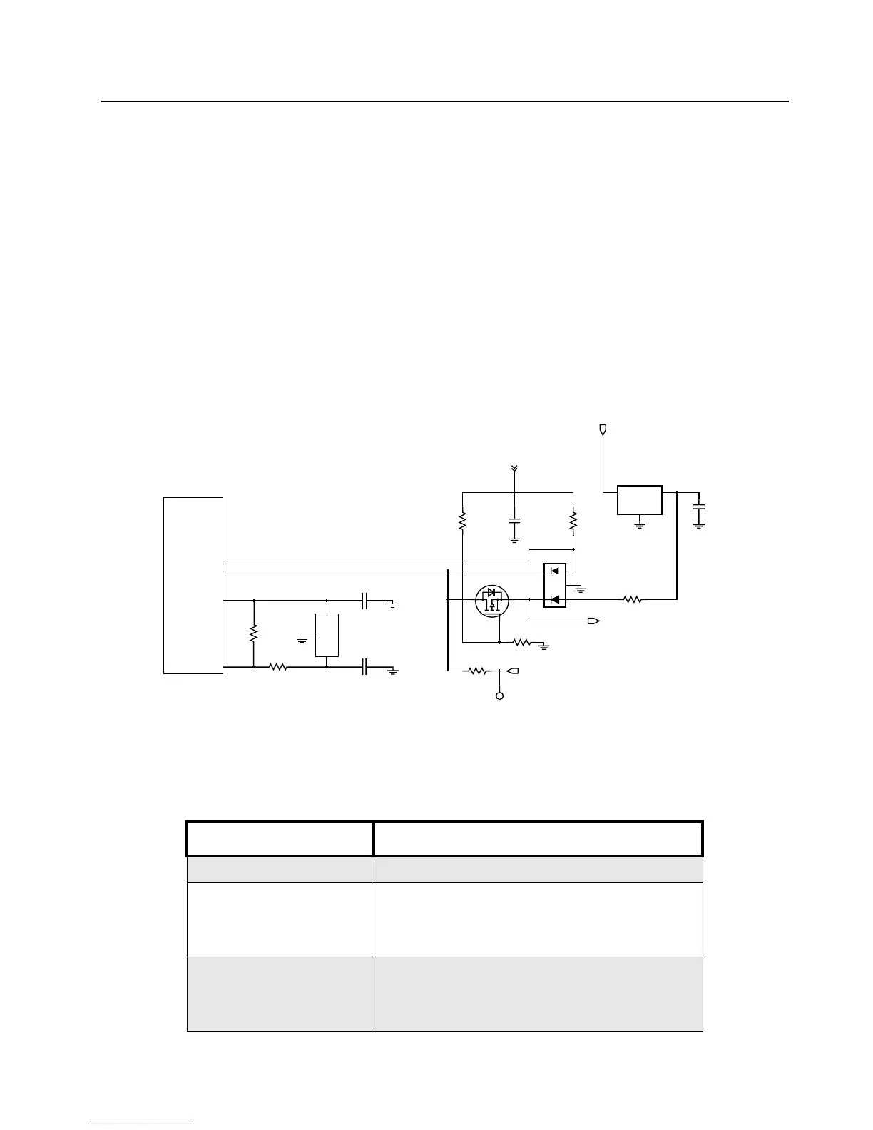
3.1.3 Circuit Description
The RTC module circuit, shown in Figure 3-3, is powered by the MODB/VSTBY pin and PI6/PI7 from
the crystal oscillator circuit. A clock frequency of 38.4 kHz from a crystal oscillator provides the
reference signal which is divided down to 1 Hz in the processor.
As the RTC module is powered separately from the processor Vdd, the RTC is kept active through
the MODB/VSTBY pin which provides the lithium-ion battery back-up power when the radio is
switched off.
A MOSFET transistor (Q416) switches in the battery supply when Vdd is removed. Q416 also
provides isolation from BOOT_CTRL function. The 3.3 V regulator charges the lithium-ion battery.
Figure 3-3. RTC Circuit
3.1.4 MODB/VSTBY Supply
The supply to the MODB/VSTBY pin varies depending on the conditions listed in Table 3- 2 .
Table 3-2. MODB/VSTBY Supply Modes
Condition Circuit Operation
Radio On Vddd supply voltage via CR411
Radio Off • Vddd turned off
• Q416 gate pulled low by R462
• Q416 switched on
• U410 supplies 3.2V to MODB_VSTBY
Primary battery removed • Vddd turned off
• Q416 gate pulled low by R462
• Q416 switched on
• Lithium-ion battery provides 3.2V to MODB_VSTBY
TP405
BOOT_CTRL
R463
LI_ION
R462
R419
3
4
2
15
CR411
1
2
3
Q416
C43
U410
3.3V
3
2
1
VIN
VOUT
VSS
UNSWB+
R460
C435
R461
Vddd
HC11FL0
MODA
MODB
R420
R426
FL401
C436
C437
PI6
PI7
OUT
IN
GND
38.4kHz

 Loading...


