EasyManuals Logo

Motorola HT Series User Manual

Motorola HT Series
639 pages
To Next Page IconTo Next Page
To Previous Page IconTo Previous Page
Page #549 background imageLoading...
Page #549 background image
Low Band Circuit Board/Schematic Diagrams and Parts List 9-399
0.78 Vdc
-24.5 dBm
3.24 Vdc
33 mV
3.25 Vdc
-24.5 dBm
-26.5 dBm
-18.75 dBm
PREAMP
LP FILTER
MIXER
56pF
C515
C536
27pF
3.6K
TP500
R510
XFMR
T502
4
6
3
12
Q509
C516
HP415
D501
2
34
1
30pF
150nH
L501
39pF
C533
82pF
C538
R505
560
2pF
C535
L504
560nH
K
2
R504
12K
D502
R503
1K
C506
100pF
L507
68nH
L508
150nH
R512
4.7K
SHIELD
SH500
SHIELD
SH501
3
1
2
R507
270
T501
4
6
270nH
L502
XFMR
.01uF
C522
SHIELD
SH502
R509
270
1uH
3.9pF
C537
L503
R508
18
C534
10
8.2pF
0.1uF
R513
C507
R
X_IN
RX_INJ
C504
51pF
IF
R5
RECEIVE -47dBm SIGNAL AT 35.04MHz WITH 1K TONE.
RF MEASUREMENTS MADE WITH BOONTON 92 MILLIVOLTMETER.
FL0830471O
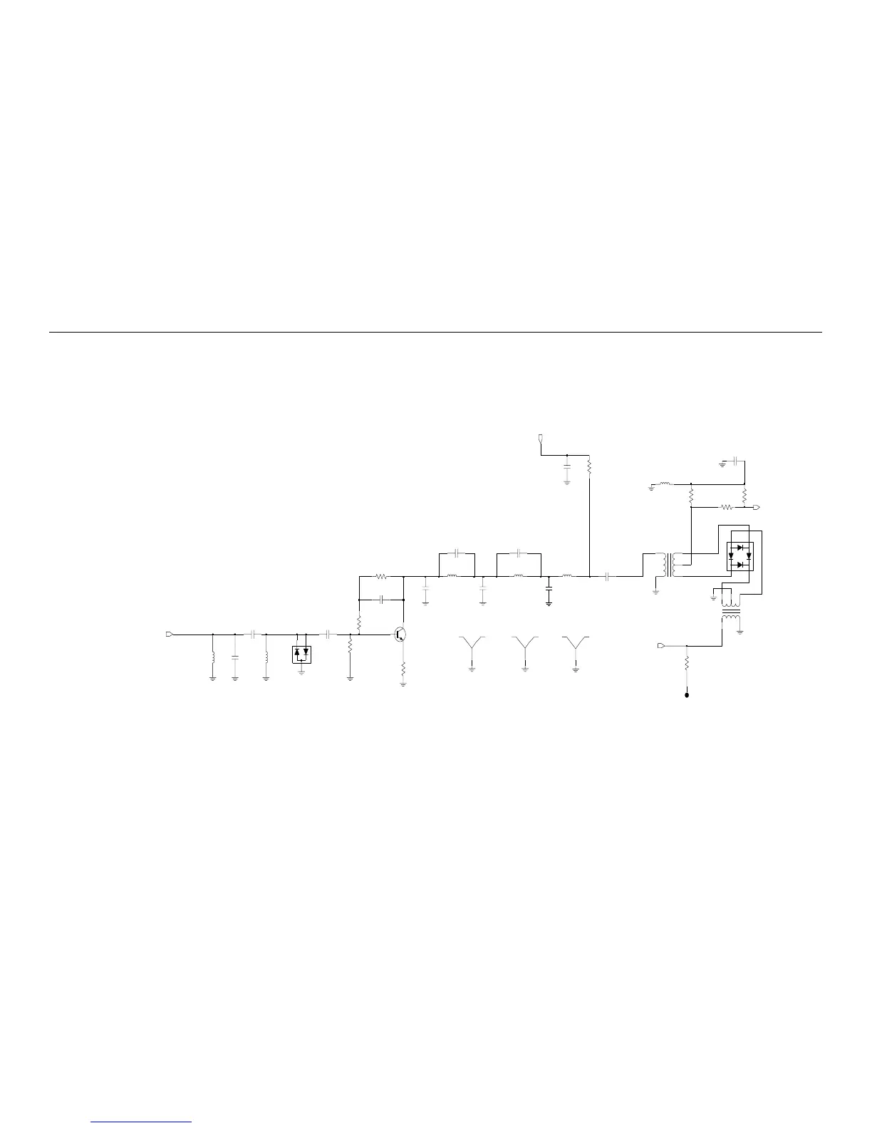
Figure 9-246. Low Band (29.7-42/35-50 MHz) Receiver Front End Schematic Diagram

Table of Contents

Other manuals for Motorola HT Series

Questions and Answers:

Question and Answer IconNeed help?

Do you have a question about the Motorola HT Series and is the answer not in the manual?

Motorola HT Series Specifications

General IconGeneral
Battery TypeLi-Ion
WaterproofIP54
Operating Temperature-30°C to +60°C
Frequency RangeVHF: 136-174 MHz
Number of Channels16

Related product manuals