Maintenance 3-5
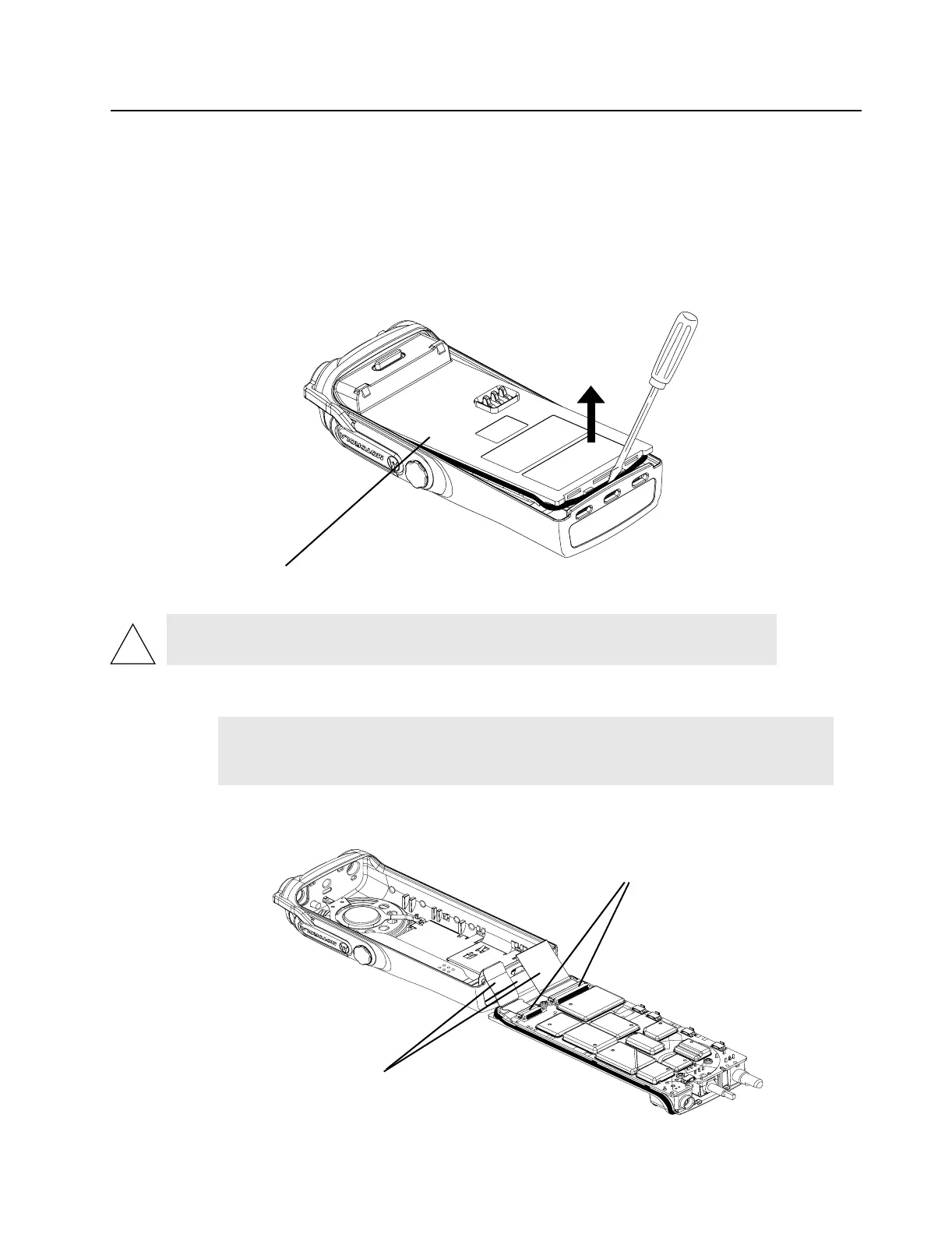
5. Separate the chassis from the internal electronics front cover assembly as follows:
a. Insert the portable chassis removal tool, 6680702Z01, or similar instrument, in between the
thin remaining wall and the chassis at the bottom of the radio. Do not mar the O-ring sealing
area on the housing.
b. Slowly pry the bottom of the chassis from the cover by pushing the portable chassis removal
tool down, and rotating the handle of the tool over and behind the base of the radio. This
prying action forces the thin inner plastic wall toward the base of the radio, releasing the two
chassis base tabs.
Figure 3-3. Chassis Removal
6. Lay the chassis down. Rotate the front cover backward and slightly away from the chassis.
7. Lift the latches on the main circuit board to release the flexes from their connectors.
Figure 3-4. Unlatch Flex Connectors
CAUTION: Marring the front cover O-ring sealing area will prevent the radio from
sealing properly.
NOTE
Flexible ribbon circuits (flexes) connecting the front cover assembly and the
chassis prevent you from completely separating the two units. Display radios and
radios with option boards have two flexes.
Radio
Flex Connector
Latches
 Loading...


