5-2 Radio Tuning, Programming, Cloning, PassPort Tone Options and Diagnostic Functions
5.2 Global Radio Tuning Setup
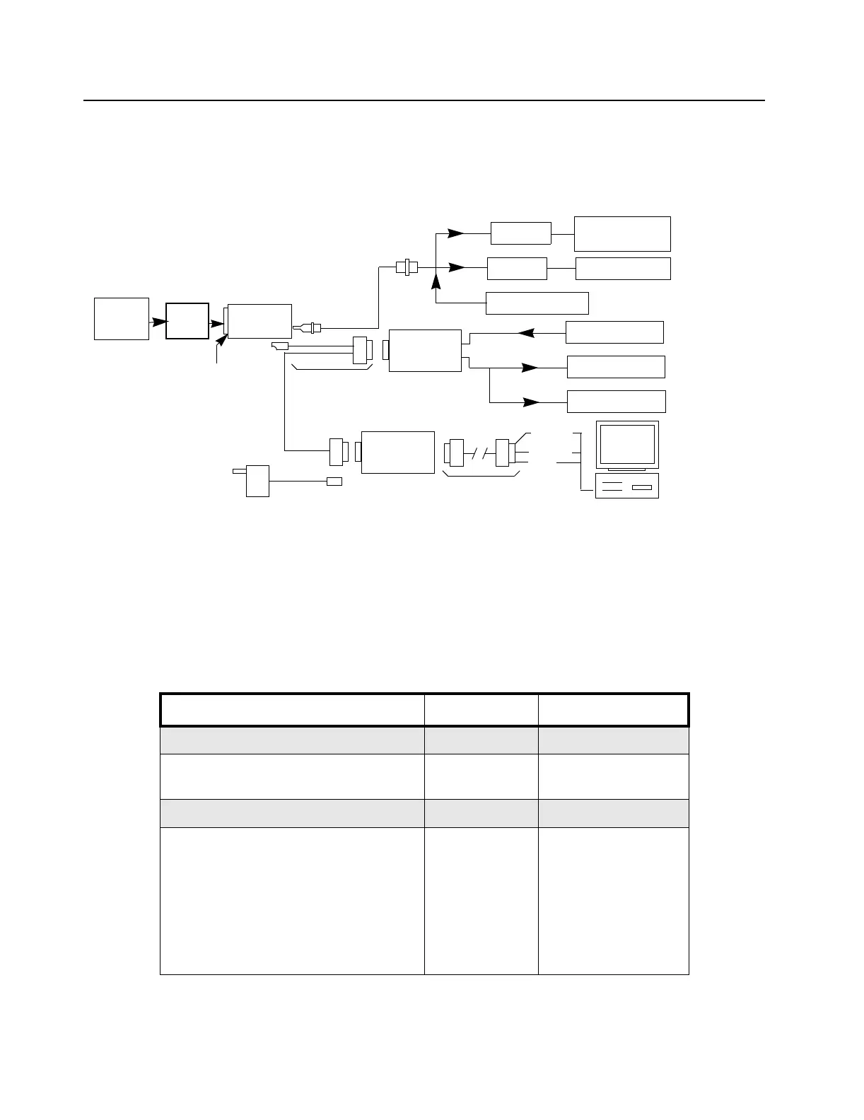
A personal computer (PC), a supported Windows
®
environment, and a global tuner program are
required to tune the radio. To perform the tuning procedures, the radio must be connected to the PC,
radio interface box (RIB), and test equipment shown in Figure 5-1.
Figure 5-1. Radio Tuning Test Equipment Setup
5.2.1 Initial Test Equipment Setup
The supply voltage is connected to the radio using a Motorola battery eliminator, P/N
AA0180305G54. The initial test equipment (Figure 5-1) control settings are listed in Table 5-2.
Note: Refer to appropriate program on-line help files for the tuning procedures.
Table 5-2. Initial Equipment Control Settings
Service Monitor Test Set Power Supply
Monitor Mode: Power Monitor Speaker set: A Voltage: 7.5 Vdc
RF Attenuation: -70 Speaker/load:
Speaker
DC on/standby:
Standby
AM, CW, FM: FM PTT: OFF Volt Range: 10 V
Oscilloscope Source: Mod
Oscilloscope Horizontal: 10 mSec/Div
Oscilloscope Vertical: 2.5 kHz/Div
Oscilloscope Trigger: Auto
Monitor Image: Hi
Monitor BW: Nar
Monitor Squelch: mid CW
Monitor Volume: 1/4 CW
Current: 2.5 A
Wattmeter
Audio Generator
Sinad Meter
AC Voltmeter
30 dB Pad
30 dB Pad
Battery
Block
Power
Supply
Audio In
Tx
Rx
Receive
Transmit
RF Generator
BNC
RF Adapter
HLN9756
RIB
RLN-4008
RIB Power Supply
RLN4460A
Test Box
Rx
Gnd
Data
Tx Data
Radio
Computer Interface
Cable 3080369B72
Program/
AARKN 4074
Test Cable
Service Monitor
or Counter
DB15 DB9
AC Plug
120/230 V ac
or B
3.5 mm to
Ferrule BNC
Double Male
RLN4510
+12 V dc
0180305G54
Battery
Eliminator
7.5 V Reg.
0180357A57 (120 V)
0180358A56 (230 V)
 Loading...


