Installation
4
Figure 2
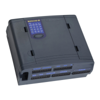
Dimensions of MOSCAD
-M RTU Plastic Case
The unit can be installed on screws or on DIN rail mounting. Before installing the
MOSCAD-M RTU, verify that there is sufficient space around the unit. Allow 20 cm (7.87")
from the bottom of the box for the TB connectors. When an RF connector is attached (internal
radio models), allow for an extra 10 cm (4"): 2.02 cm (.8") from the top of the box for the RF
connector and 8 cm (3.15") for the wires. For models with external radios, allow 8 cm (3.15").
Wall Mounting with Screws
The MOSCAD-M can be mounted on the wall using screws, as shown in Figure 3.
1. Secure two screws (maximum head size 0.9 mm) on the wall, 105 mm apart.
2. Hang the unit on the screws, fitting the two cavities on the back cover of the unit over the
screws (see Figure 3).
The screws used should not protrude from the wall surface by more than 6 mm or by less than
4 mm.

 Loading...