CHAPTER 4 ELECTRICAL INTERFACE
Introduction
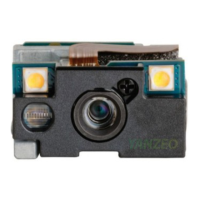
Table 4-1 lists the pins and signals of the 21-pin connector on the SE4750. See Figure 2-4 on page 2-6 for the
pin 1 location on the rear of the engine, on the side opposite the aiming/illumination system.
Table 4-1
SE4750 Parallel Host Interface Signal Information
Pin Number SE4750 Signal Name I/O Notes
1GND -Ground
2GND -Ground
3 I2C_CLK I
I
2
C clock
4 I2C_DATA I/O
I
2
C data
5 VSYNC O Vertical sync
6 PIX_DATA_7 O Sensor pixel data - MSB
7 PIX_DATA_6 O Sensor pixel data
8 PIX_DATA_5 O Sensor pixel data
9 PIX_DATA_4 O Sensor pixel data
10 PIX_DATA_3 O Sensor pixel data
11 PIX_DATA_2 O Sensor pixel data
12 PIX_DATA_1 O Sensor pixel data
13 PIX_DATA_0 O Sensor pixel data - LSB
14 EXT_ILLUM_EN O External illumination trigger
15 VDD_IO_HOST PWR In Host digital logic level
16 VCC PWR In Aiming and logic power
 Loading...