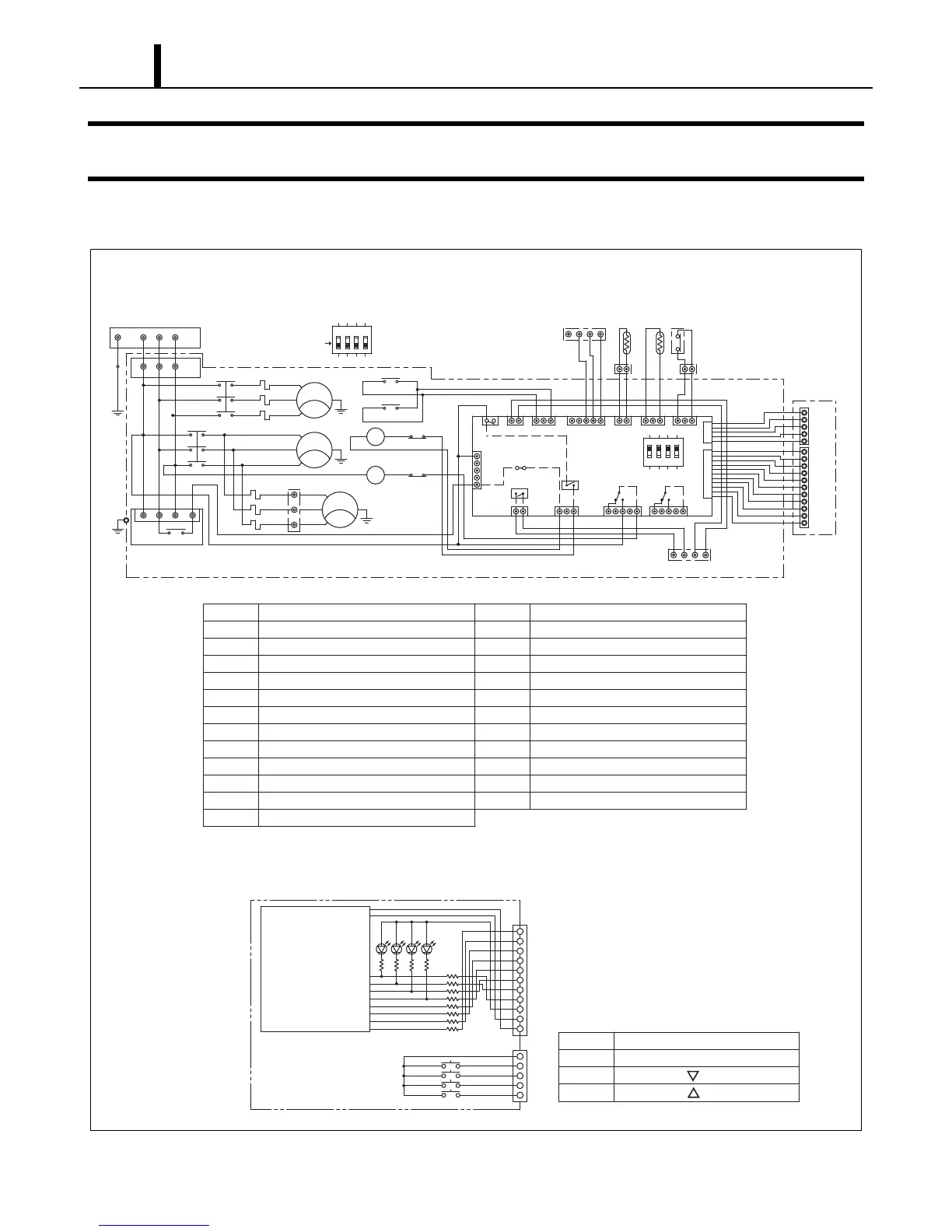
5. ELECTRICAL SYSTEM
I003091
SW1 COOL ON/OFF Switch
Control Board
DIG
SW2 FAN Switch
SW3 SET TEMP Switch
SW4 SET TEMP Switch
SW1
CN8
SW2
SW3
SW4
4
5
3
2
1
CN9
R101
R102
R103
R104
R109
R110
R112
R111
LED1
LED2
LED4
LED3
R105
R106
R107
10
11
9
8
7
4
5
6
3
2
1
R108
RST
CN03
MF2
1
3
5
CN16
1
TB3
5
(G)
2
4
6
(95)
External
Controller
GY
AP
RC
TB1
RPHR
(R)
CN1
MCC
OCF1
OCF2 TB4
31
Fire Alarm
Input
On Board
Controller
OCF2
(U22)
(97)
1312213
1
(V22)
HPRS
CN3
1
11
5
1
5
1
13
23
33
11
TB2
E+E-L+L-
R
CB
MCF
MCC
MF1
MC
MCF
ST
1
(S)
AC220 V, 3 Phase, 60 Hz
(T)
(U11)
14
24
34
1
3
5
2
4
6
1
1
3
5
2
4
6
G
1
A2
A1
A1 A2
52ID
(V11)
OCF2
(W11)
CN01
5
(96)
(95)
OCF1
(96)
(G)
(G)
1234
1
5
F1
12
CN22
52OD1
CN23
52OD2
CN21
31
CN13
CN2
RB
RTS CTS
Control Box
5
CN15
CN11
CN12
CN17
CN25
R
Output
Signal
(G)
T
34
52CM
220 V
COM
CN24
52CT
ON
Dip Switch
ON
Off (Default)
Dip Switch
#1 : On : Fan Stop Mode (Fan Auto)
Off : Fan Operate Mode (Fan On)
#2 : N/A
#3 : N/A
#4 : On : The Buzzer Sound Disabled
1234
(98)
OCF1
(97) (98)
IOLC
IOLF2
IOLF1
(G)
(W22)
AP Attachment Plug
TB1 Terminal Block
TB2 Terminal Block
TB3 Terminal Block
TB4 Terminal Block
MF1 Evaporator Fan Motor
MF2 Condenser Fan Motor
G
IOLF1
RPHR Reverse Phase Protector
MCF Fan Motor Relay
MCC Compressor Motor Relay
HPRS High Pressure Switch
OCF1 Overcurrent Relay MF1
OCF2 Overcurrent Relay MF2
MC Compressor Motor
RB Relay Board
CTS Freeze Protection Thermistor
CB Control Board
Grounding
RTS Room Thermistor
CN3
CN1 Connector for RPHR
CN2 Connector for RTS
Connector for HPRS
Inner Overload Relay of MF1
IOLC
IOLF2 Inner Overload Relay of MF2
Inner Overload Relay of Compressor