- 10 -
You must enable the Turbo Ring function first before using the
DIP switch to activate the Master and Coupler functions.
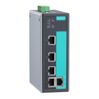
LED Indicators
There are several LEDs on the EDS’s front panel. The function of each LED
is described in the following table.
STATE
GREEN
On
self-diagnosis test on boot-up and
Blinking
The switch is under reset progress
(1 time/s)
RED
On
Blinking
The system self-diagnosis fails on
boot-up.
1. RAM Test Fail / System Info Read
Fail / Switch Init./PTP PHY error Fail
(+ Green MSTR lit on : HW FAIL)
2. FW Checksum Fail / Uncompress
Fail
(+ Green Coupler lit on: SW FAIL)
PWR1 AMBER
On
Power is being supplied to power
input PWR1.
Off
Power is not being supplied to
power input PWR1.
PWR2 AMBER
On
Power is being supplied to power
input PWR2.
Off
Power is not being supplied to
FAULT RED On
1. The signal contact is open.
2. The port being disabled because
of the ingress multicast and
broadcast packets exceed the
ingress rate limit
3. Incorrect loop connection in a
single switch
4. Invalid Ring port connection
MSTR/HEAD GREEN
On
1. The switch is set as the Master of
the Turbo Ring, or as the Head of
the Turbo Chain.
2. POST H.W. Fail (+Stat on and
Blinking
1. The switch has become the Ring
Master of the Turbo Ring
2. The Head of the Turbo Chain,
after the Turbo Ring or the Turbo
Chain is down.
3. The switch is set as Turbo
Chain’s Member and the
corresponding chain port is down.
Off
1. The switch is not the Master of
this Turbo Ring.
2.
This switch is set as a Member of
the Turbo Chain.

 Loading...