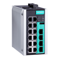
FAULT:
The two contacts of the 6
pin terminal
block connector are used to detect
user
configured events. The two wires
attached to the
ault contacts form an
open circuit when a user
event is triggered. If a user
configured
event does not occur, the
Wiring the Redundant Power Inputs
The EDS-G500E series has two sets of power inputs—power input 1 and
power input 2. The top and front views of one of the terminal block
connectors are shown here.
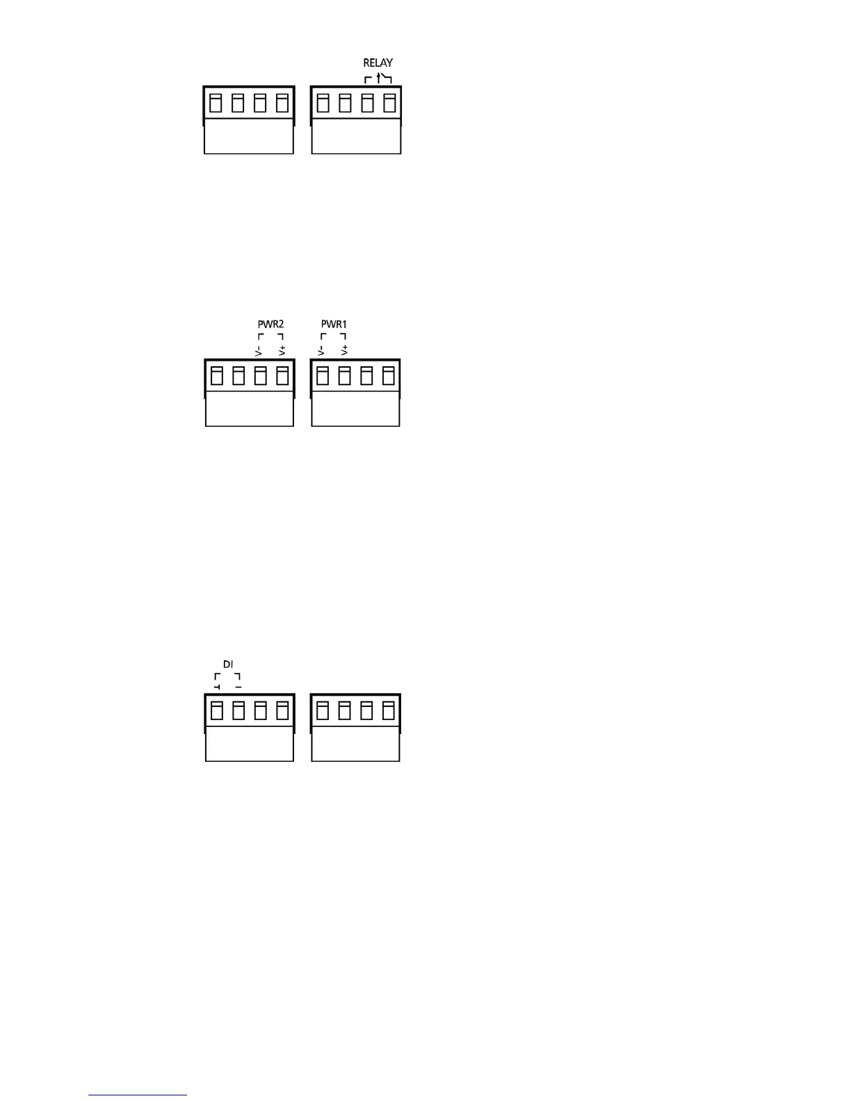
STEP 1: Insert the negative/positive
DC wires into the V
To keep the DC wires from
pulling loose, use a small flat
screwdriver to tighten the wire
clamp
screws on the front of the terminal
block connector.
Insert the plastic terminal
block connector prongs into the
terminal block receptor, which is
located on the EDS-G500E’s top panel.
Wiring the Digital Inputs
The EDS-G500E series has one set of digital input (DI). The DI consists of
two contacts of the 4-pin terminal block connector on the EDS-G500E's
top panel, which are used for the two DC inputs. The top and front views
of one of the terminal block connectors are shown here.
STEP 1: Insert the negative
(ground)/positive DI wires into the
/I terminals, respectively.
To keep the DI wires from
pulling loose, use a small flat
screwdriver to tighten the wire
clamp
screws on the front of the terminal
block connector.
Insert the plastic terminal
block connector prongs into the
terminal block receptor,
located on the EDS-G500E’s top panel.
Communication Connections
Each EDS-G500E series switch has 4 types of communication ports:
• 1 USB console port (type B connector)
• 1 USB storage port (type A connector)
• 8 (EDS-G508E/EDS-G512E-4GSFP) or 12 (EDS-G516E-4GSFP)
10/100/1000BaseT(X) Ethernet ports
• 4 100/1000Base SFP slots (EDS-G512E-4GSFP/EDS-G516E-4GSFP)
 Loading...