- 7 -
Wall Mounting (Optional)
For some applications, you will find it convenient to mount Moxa EDS-
G500E series on the wall, as shown in the following illustrations:
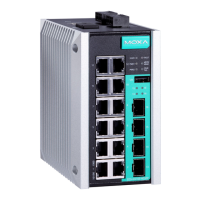
STEP 1—Remove the
aluminum DIN rail attachment
plate from the rear panel
then attach the wall mount
plates
Mounting the EDS-G500E series on the
wall requires 4 screws. Use the
,
with wall mount plates attached, as a guide to
mark the correct locations of the 4 screws. The
heads of the screws should be less than 6.0 mm
in
diameter, and the shafts should be less than 3.5
mm in diameter, as shown in the figure on at right.
Before tightening the screws into the wall, make sure the screw
head and shank size are suitable by inserting the screw through
one of the keyhole-shaped apertures of the Wall Mounting Plates.
Do not screw the screws in all the way—leave about 2 mm to allow room
for sliding the wall mount panel between the wall and the screws.
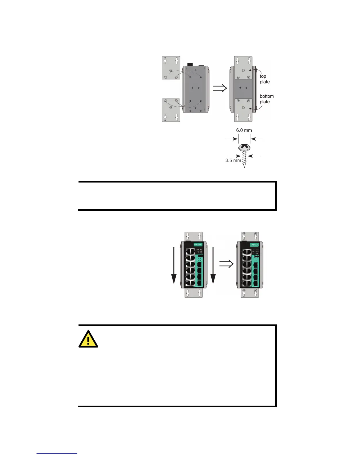
STEP 3—Once the screws are
fixed
four screw heads through the
wide parts of the
keyhole
G500E
downwards, as indicated
the right. Tighten
the four screws for
Do not disconnect modules or wires unless power has been
switched off or the area is known to be non
devices may only be connected to the supply voltage shown on
the type plate. The devices are designed
oltage. Thus, they may only be connected to
the supply voltage connections and to the signal contact with the
S
afety Extra-Low Voltages (SELV) in compliance with IEC950/
 Loading...