- 11 -
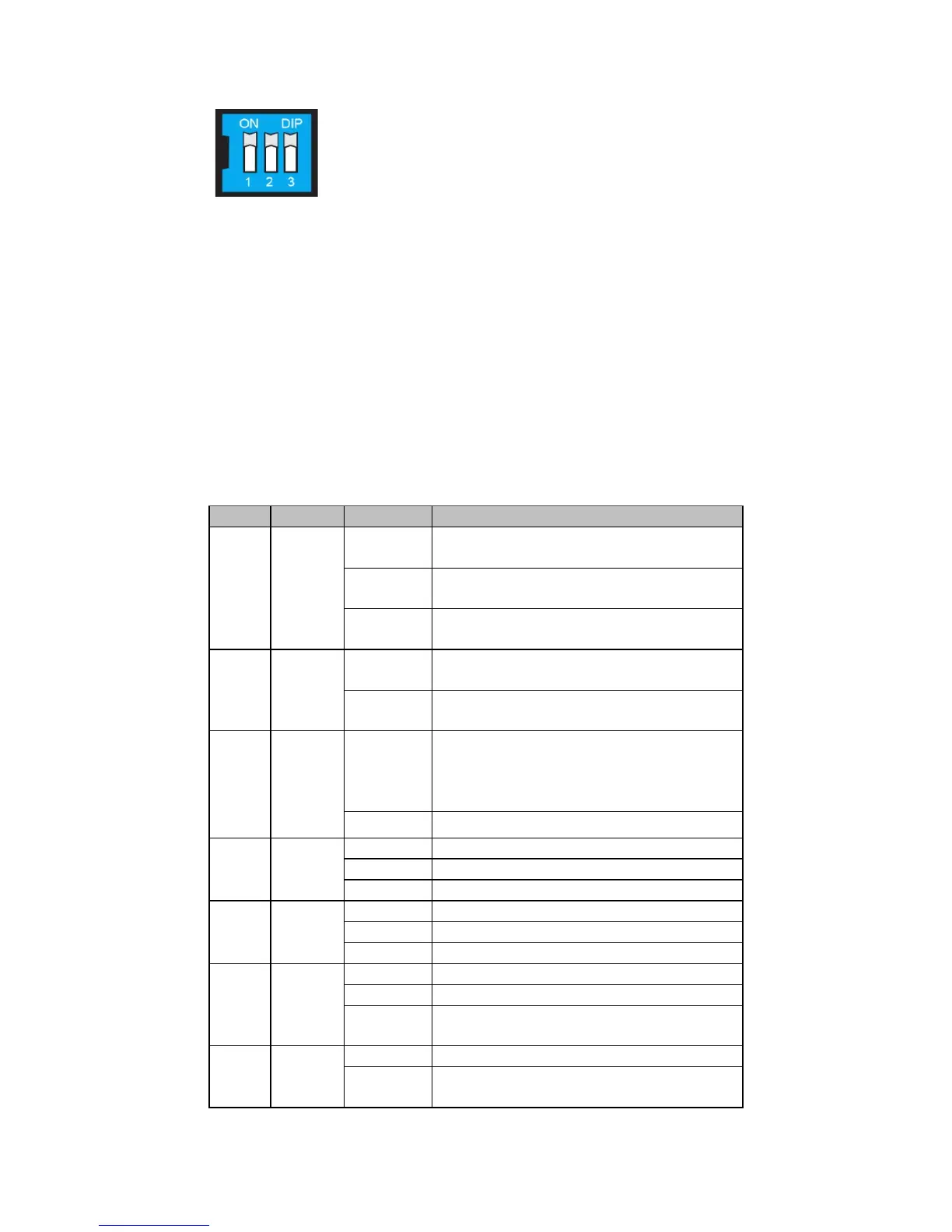
Dip Switch Setting
Dip Switch 1 (Default: Off)
ON: Enables the PORT Alarm. If the port’s link fails, the
relay will form an open circuit and the fault LED will
light up.
Off: Disables the corresponding PORT Alarm. The relay
will form a closed circuit and the Fault LED will never
light up.
Dip Switch 2 (Default: ON)
ON: Enables full duplex for 100BaseFX
Off: Disables full duplex for 100BaseFX
To activate the updated DIP switch setting, power off and then power on
the IMC-101.
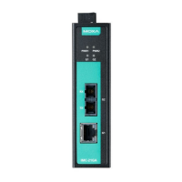
LED Indicators
The front panel of the IMC-101 contains several LED indicators. The
function of each LED is described in the table below.
Power is being supplied to power input
PWR1
Power is not being supplied to power input
PWR1
On
Power is being supplied to power input
Power is not being supplied to power input
PWR2
When the corresponding PORT alarm is
enabled, and the port’s link is inactive.
When the corresponding PORT alarm is
enabled and the port’s link is active, or
when the corresponding PORT alarm is
On
TP port’s 10 Mbps link is active
10M
(TP)
GREEN
Data is being transmitted at 10 Mbps
TP Port’s 10 Mbps link is inactive
TP port’s 100 Mbps link is active
Data is being transmitted at 100 Mbps
100BaseTX Port’s link is inactive
FX port’s 100 Mbps is active
Data is being transmitted at 100 Mbps
100BaseFX port is inactive
100BaseFX port is being transmitted at full
duplex
100BaseFX port is being transmitted at
half duplex
 Loading...