EasyManuals Logo

Moxa Technologies IMC-101 Series User Manual

Moxa Technologies IMC-101 Series
14 pages
To Next Page IconTo Next Page
To Previous Page IconTo Previous Page
Page #3 background image
- 3 -
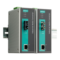
Panel Layout of IMC-101 Series
1. Grounding screw
2.
Terminal block for power input
PWR1/PWR2 and relay output
3. Heat dissipation vents
4. Dip switch
5. Power input PWR1 LED
6. Power input PWR2 LED
7. Fault LED
8. 100BaseFX (ST connector)
Port
9. FX port’s 100 Mbps LED
10.
FX port’s Full Duplex/Collision
LED
11.
TP port’s 100 Mbps LED
12.
10/100BaseT(X)
13.
TP port’s 10 Mbps LED
14.
Model Name
15.
100BaseFX (SC connector)
Port
16.
Screw hole for wall mounting
kit
17.
DIN rail mounting kit

Questions and Answers:

Question and Answer IconNeed help?

Do you have a question about the Moxa Technologies IMC-101 Series and is the answer not in the manual?

Moxa Technologies IMC-101 Series Specifications

General IconGeneral
Storage Temperature-40 to 85°C (-40 to 185°F)
Humidity5 to 95% (non-condensing)
Ports1 x 10/100BaseT(X) port, 1 x 100BaseFX port
Fiber TypeMulti-mode or Single-mode
Transfer Distance2 km (Multi-mode)
Power Input12 to 48 VDC
Operating Temperature-40 to 75°C (-40 to 167°F)
CertificationsCE, FCC, UL
StandardsIEEE 802.3

Related product manuals