- 5 -
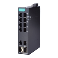
Wiring the Relay Contact
Each PT switch has one relay output. Refer to the next section for detailed
instructions on how to connect the wires to the terminal block connector, and
how to attach the terminal block connector to the terminal block receptor.
FAULT: The relay contact of the 10-pin terminal block connector are used to
detect user-configured events. The two wires attached to the RELAY contacts
form an open circuit when a user-configured event is triggered. If a
user-configured event does not occur, the RELAY circuit will be closed.
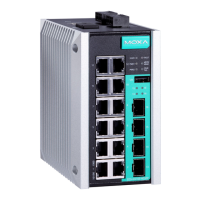
Wiring the Redundant Power Inputs
Each PT switch has two sets of power inputs: power input 1 and power input 2.
STEP 1: Insert the dual set positive/negative DC wires into PWR1 and PWR2
terminals (+ → pins 1, 9; - → pins 2, 10). Or insert the L/N AC wires into
PWR1 and PWR2 terminals (L → pin 1, 9; N → pin 2,10)
STEP 2: To keep the DC or AC wires from pulling loose, use a screwdriver to
tighten the wire-clamp screws on the front of the terminal block connector.
Note 1: The PT switch with dual power supplies uses PWR2 as the first
priority power input by default.
Note 2: For dielectric strength (HIPOT) test, users must remove the metal
jumper located on terminals 3, 4, and 7, 8 of the terminal block to avoid
damage.

 Loading...