MP sava3 Hidraulic Power Unit 1 ¼” 1 ½”
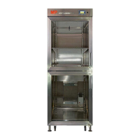
A Point Upwards deceleration signal.
Place at an S distance from the floor level equal to
B Point Motor disconnected signal.
C Point Downwards deceleration signal.
Place at an S distance from the floor level equal to
D Point YD Electrovalve disconnection signal
For direct starting, motor idle time approx. 0,5 seconds
Change to D
Connect in Y for 2 seconds approx
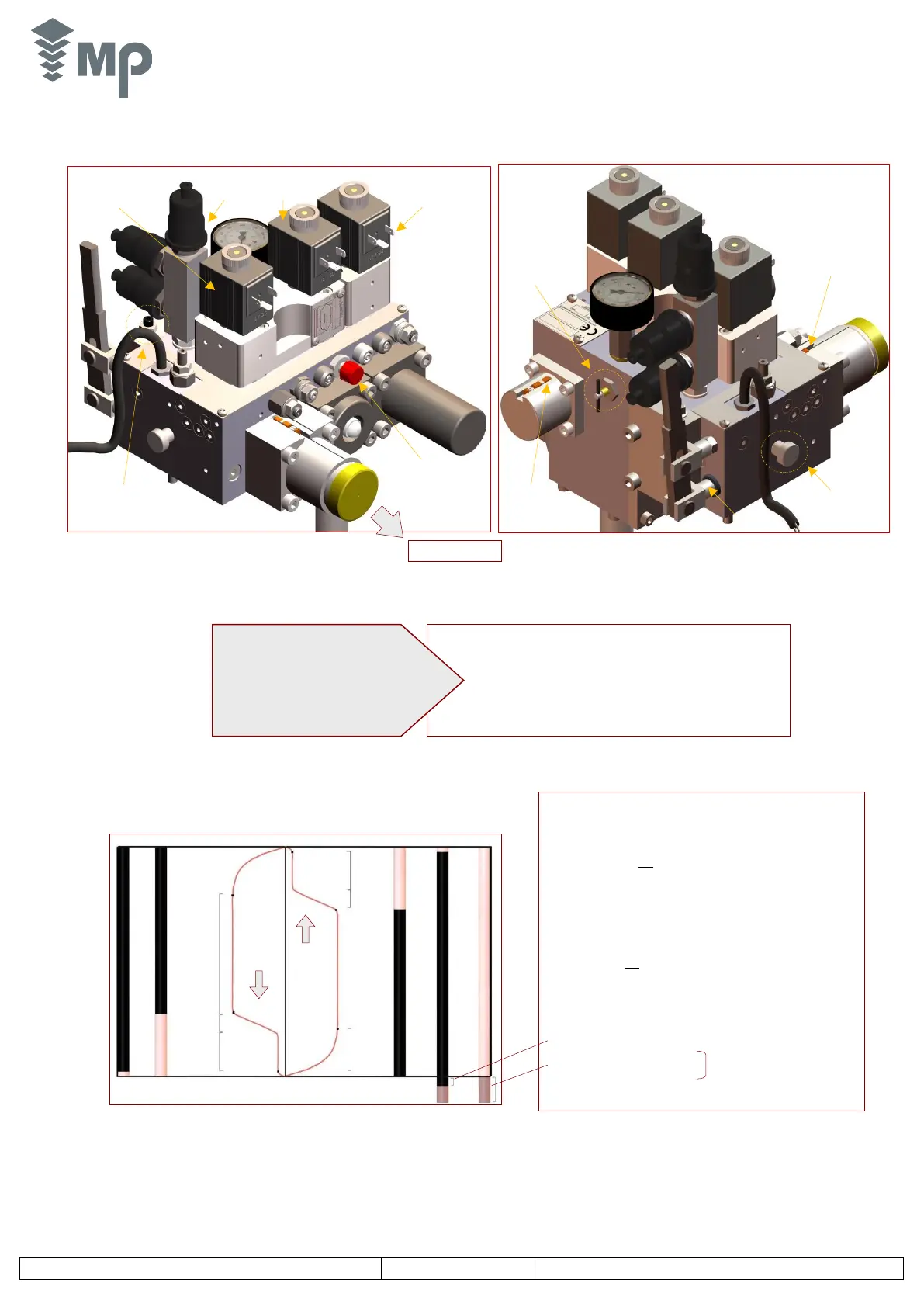
2.2. MP sava3 Valve Block
2.2.1. Description of Valves
2.2.2. Unit operation
1: Pressure relief valve adjustment
2: Upwards acceleration adjustment
3: Upwards/downwards deceleration adjustment
4: Levelling speed adjustment
5: Down speed adjustment
6: Cylinder minimum pressure adjustment.
7: Hand pump relief valve adjustment.
YD Electrovalve
(descent)
+ YE (emergency)
YR Electrovalve
(for speed
change)
Pressure switch
with adjustment
screw
Testing screw
of the rupture
valve
Manual lowering
pushbutton
Starting
Electrovalve YS
(-A3 optional)
Magnetic Sensor
Descent Valve
SVD
Magnetic Sensor
Bypass Valve
SVC