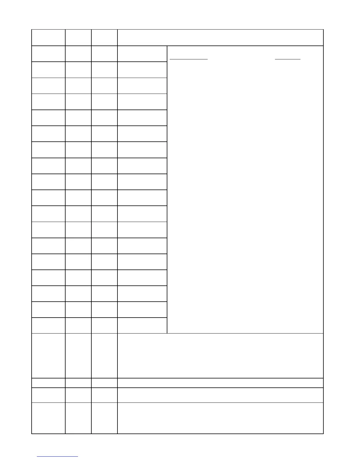
5
Parameter
Default
Value
Current
Value Setting Definitions
F.01
1
Discrete Input 1
Function
F.02
2
Discrete Input 2
Function
F.03
3
Discrete Input 3
Function
F.04
4
Discrete Input 4
Function
F.05
5
Discrete Input 5
Function
F.06
6
Discrete Input 6
Function
F.07
7
Discrete Input 7
Function
F.08
8
Discrete Input 8
Function
F.09
9
Discrete Input 9
Function
F.10
10
Discrete Input 10
Function
F.11
11
Discrete Input 11
Function
F.12
12
Discrete Input 12
Function
F.13
13
Discrete Input 13
Function
F.14
14
Discrete Input 14
Function
F.15
15
Discrete Input 15
Function
F.16
16
Discrete Input 16
Function
F.17
17
Discrete Input 17
Function
F.18
18
Discrete Input 18
Function
F.19
1
Level Input Source
1 = Analog Level Input (4-20mA) on J21
2 = Level Probe Input on J25
3 = Level Probe Input on J25 (Flashes Level Probe Electrode No. of Level Settings.)
4 = Remote Level Input (Follows the Level written to SCADA Register 40025.)
Note: Level Probe not suitable for applications measuring Storm Water or Well Water.
Function of Input: Connect To:
0 = No Function
1 = Pump 1 Disable …….………...…………...…. HOA and Fault Logic
2 = Pump 2 Disable …….….....…..……….….….. HOA and Fault Logic
3 = Pump 3 Disable ………..……..…….…..…..... HOA and Fault Logic
4 = Pump 4 Disable …….….…..………….….….. HOA and Fault Logic
5 = Level Freeze ……………...………....…. Bubbler Tube Purge Logic
6 = External Alternation ………...……......………. External Time Clock
7 = On Generator ………………….……….. Automatic Transfer Switch
8 = All Pump Disable …………...…………...…………... Phase Monitor
9 = Sequence Input 1 ……....…..…… Lead Select Switch - 1 as Lead
10 = Sequence Input 2 ….…….........… Lead Select Switch - 2 as Lead
11 = Sequence Input 3 …...…...…….… Lead Select Switch - 3 as Lead
12 = Sequence Input 4 ….……......…… Lead Select Switch - 4 as Lead
13 = Call Pump 1 Last ……...…….………...…………..…. Logic Contact
14 = Call Pump 2 Last ……...……………....…………..…. Logic Contact
15 = Call Pump 3 Last …….…….……..…...…………..…. Logic Contact
16 = Call Pump 4 Last …….………….….....…………..…. Logic Contact
17 = Low Level Alarm ……..………..…..…….… Low Level Float Switch
18 = High Level Alarm …………………...…..… High Level Float Switch
19 = Telemetry E ………...…………………....……… Telemetry Contact
20 = Telemetry F …….………………….....…….…… Telemetry Contact
21 = Telemetry G ……..……………………........…… Telemetry Contact
22 = Telemetry H …………………………...………… Telemetry Contact
23 = Telemetry J ………………………….…..….…… Telemetry Contact
24 = Telemetry K ……………………………...……… Telemetry Contact
25 = Telemetry L ……………………….…..….……… Telemetry Contact
26 = Telemetry M ………………………..……….…… Telemetry Contact
27 = Telemetry A ………………………..….…….…… Telemetry Contact
28 = Telemetry B ……………………...….….…..…… Telemetry Contact
29 = Telemetry C ……….…………………...…...…… Telemetry Contact
30 = Telemetry D ………………………...…..……..… Telemetry Contact
31 = Normal Pump Operation Disable ......................…..
.. Fault Contact
32 = Float Backup – Low Level .….………........ Low Level Float Switch
33 = Float Backup – Off Level ….……….….….... Off Level Float Switch
34 = Float Backup – 1ST
On Level ……...... 1ST On Level Float Switch
35 = Float Backup – 2ND
On Level ……..... 2ND On Level Float Switch
36 = Float Backup – 3RD
On Level ……..... 3RD On Level Float Switch
37 = Float Backup – 4TH
On Level ……...... 4TH On Level Float Switch
38 = Float Backup – High Level .………...…..... High Level Float Switch
39 = Start Flush Cycle …………………...……...…. External Time Clock
Notes:
1. Function of Discrete Inputs may be set to “0” when Input is used
only to collect data for SCADA and no other Function is desired.
2. All Discrete Inputs may be read from SCADA Registers 40035 -
40037, regardless of the Function assigned to the Input.
3. See Pages 14 - 16 for description of each of the above Functions.
F.20
12 in. Level Probe Electrode Spacing Range: 3 - 24 inches
F.21
0.0 feet
Level Offset Range: 0.0 - 5.0 feet
Note: This adds to the Level from the Analog Level Input or Level Probe Input.
F.22
100
Level Probe Sensitivity Range: 90 - 210
100 = Typical Sewage 150 = Light Sewage
Check value of Parameter L.10 with Electrode 10 covered, add 40 to it, and enter value for F.22.
Note: Level Probe not suitable for applications measuring Storm Water or Well Water.
MENU - SYSTEM SETUP
All Level Settings Have the Decimal Point Artificially Inserted Based on Parameter P.36.
 Loading...