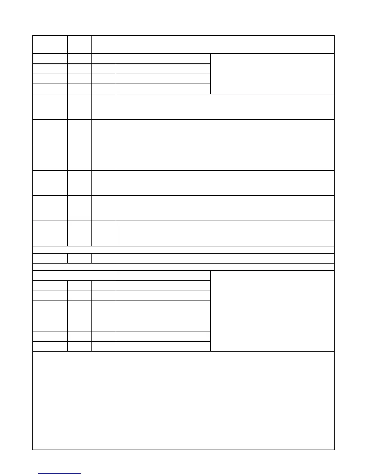
6
Parameter
Default
Value
Current
Value Setting Definitions
F.23 1 Analog Output 1 Function
1 = Pump 1 Speed (Active When Pump 1 is Called)
2 = Pump 2 Speed (Active When Pump 2 is Called)
3 = Pump 3 Speed (Active When Pump 3 is Called)
4 = Pump 4 Speed (Active When Pump 4 is Called)
5 = Speed Reference any Pump (Always Active)
6 = Copy of Wet Well Level
F.24 2 Analog Output 2 Function
F.25 3 Analog Output 3 Function
F.26 4 Analog Output 4 Function
F.31 1
HI Relay Output Function
0 = Disabled 1 = High Level Alarm 2 = Remote Control
(SCADA Coil 25)
Note: High Level indicator on front of unit will operate regardless of setting.
F.32 1
LO Relay Output Function
0 = Disabled 1 = Low Level Alarm 2 = Remote Control (SCADA Coil 26)
Note: Low Level indicator on front of unit will operate regardless of setting.
F.33
1
P1 Relay Output Function
0 = Disabled 1 = Pump 1 Call 2 = Remote Control (SCADA Coil 27)
Note: When set on “0” or “2” Pump 1 will be skipped over in all Alternation Sequence Modes.
F.34 1
P2 Relay Output Function
0 = Disabled 1 = Pump 2 Call 2 = Remote Control (SCADA Coil 28)
Note: When set on “0” or “2” Pump 2 will be skipped over in all Alternation Sequence Modes.
F.35 1
P3 Relay Output Function
0 = Disabled 1 = Pump 3 Call 2 = Remote Control (SCADA Coil 29)
Note: When set on “0” or “2” Pump 3 will be skipped over in all Alternation Sequence Modes.
F.36
1
P4 Relay Output Function
0 = Disabled 1 = Pump 4 Call 2 = Remote Control (SCADA Coil 30)
Note: When set on “0” or “2” Pump 4 will be skipped over in all Alternation Sequence Modes.
E.01
-
E.62
- Ethernet Port Setup See Page 27.
Level Probe Backup Functions
0 = Function Not Used
1 = Electrode Input 1 on Connector J25-1
2 = Electrode Input 2 on Connector J25-2
3 = Electrode Input 3 on Connector J25-3
4 = Electrode Input 4 on Connector J25-4
5 = Electrode Input 5 on Connector J25-5
6 = Electrode Input 6 on Connector J25-6
7 = Electrode Input 7 on Connector J25-7
8 = Electrode Input 8 on Connector J25-8
9 = Electrode Input 9 on Connector J25-9
10 = Electrode Input 10 on Connector J25-10
b.01 0
Low Level Alarm
b.02 0
Pump Control – Off Level
b.03 0
Pump Control – 1ST
On Level
b.04 0
Pump Control – 2ND On Level
b.05 0
Pump Control – 3RD On Level
b.06 0
Pump Control – 4TH On Level
b.07 0
High Level Alarm
Notes For Level Probe Backup Functions: For status of Level Probe inputs see Coils 583 - 592 in SCADA Register 40037.
1. When the controller is set up to follow a 10 Electrode Conductance Level Probe as the primary level input source (Parameter F.19
= 2 or 3), the backup functions described here are not needed and will not operate.
2. If a Function (such as Pump Control – 4TH On Level) is not desired set the respective parameter equal to zero.
3. An effective Backup Pump Control would involve having a 3 point Level Probe placed high in the wet well. The Level Probe would
be connected to Connector J25 terminals 1, 2, and 3. The Off Level should be made to operate from the bottom Electrode by
setting Parameter b.02 = 3. The 1ST On Level should be set to operate from Electrode 2 by setting Parameter b.03 = 2. The
2ND On Level should be set to operate from Electrode 1 by setting Parameter b.04 = 1. If additional pumps are present set the
3RD On and 4TH On Levels, to operated from Electrode 1 by setting Parameter b.05 = 1, and b.06 = 1.
4. If a Backup High Level Alarm is desired, set Parameter b.07 to the number of the Electrode Input that the High Level Probe is con-
nected to. This feature is for alarm and telemetry only and will not function as a redundant pump call. See SCADA notes page 32.
5. If a Backup Low Level Alarm is desired, set Parameter b.01 to the number of the Electrode Input that the Low Level Probe is con-
nected to. This feature is for alarm and telemetry only and will not function as a redundant pump off. See SCADA notes page 33.
6. Whenever the Backup Pump Control is active the Fault indicator will be on and fault code of 30 will be present in Parameter FLC,
and set Coil 15 in SCADA Register 40001.
MENU - SYSTEM SETUP
 Loading...