PV Module Selection:
When selecting proper PV modules, please be sure to consider the parameters below:
1. Open circuit Voltage (Voc) of PV modules can’t exceed the maximum voltage of the PV array open circuit of
the inverter.
2. Open circuit Voltage (Voc) of PV modules should be higher than the minimum voltage of the battery.
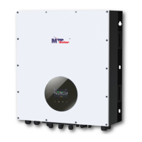
Please follow the steps below to implement PV module connection:
1. Remove insulation sleeve 10 mm from positive and negative conductors.
2. Check the correct polarity of connected cable from PV modules and PV input
connectors. Then, connect positive pole (+) of connection cable to positive
pole (+) of PV input connector. Connect negative pole (-) of connection
cable to negative pole (-) of PV input connector.
3. Make sure the wires are securely connected.
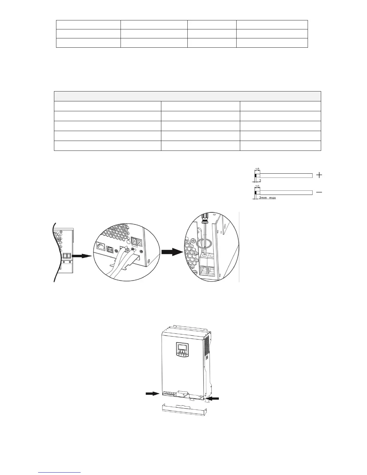
Final Assembly
After connecting all wirings, please put the bottom cover back by fixing two screws as shown below.
 Loading...