3 Product description
Maschinenfabrik Reinhausen GmbH 202020 5788897/03 ENVACUTAP
®
VVS
®
View from above
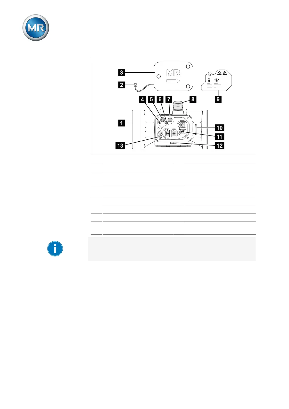
Figure7: Protective relay RS 2001
1 Gasket 2 Potential tie-in
3 Terminal box cover 4 Slotted head screw for potential
tie-in
5 OPERATION (reset) test button 6 Slotted head screw for protective
cover
7 OFF (test tripping) test button 8 Cable gland
9 Protective cover 10 Dummy plug
11 Connection terminal 12 Pressure equalization element
13 Cylinder head screw for protective
conductor connection
The protective relays RS 2003 and RS 2004 have a 1/2"-14NPT adapter in
place of the cable gland.