42
Settings Parameters
GB
Model 9010/9020 SIL
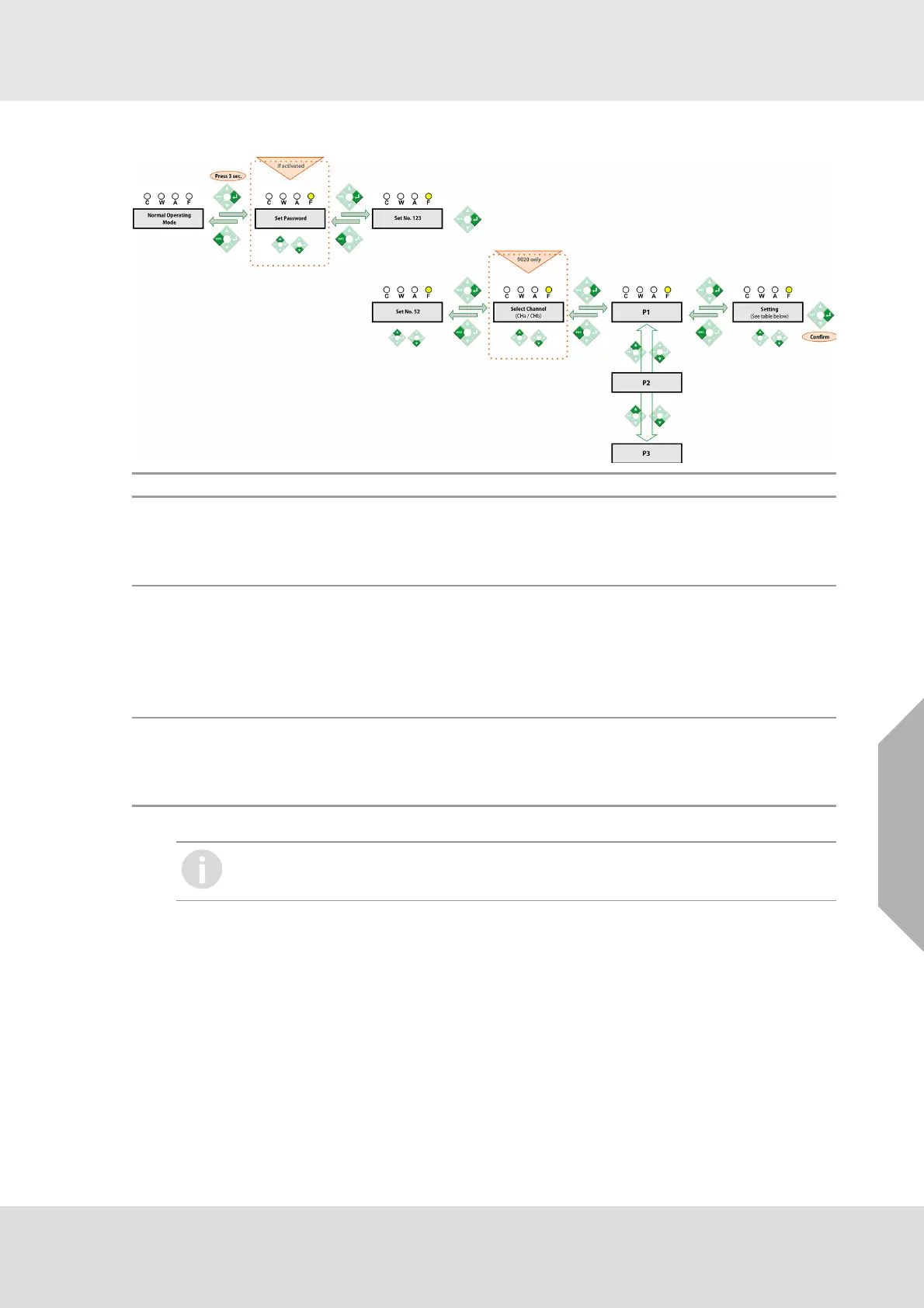
5.7 Access code 52 - Input and Output Setup
Step Function Note
P1
Digital Output Type
Define the outputs hardware configuration
1 = Relay
2 = not used
Common for both of the chan-
nels
P2
Input Signal Type
Setting the type of input signal
1 = catalytic combustion detectors
2 = 4-20 mA transmitters (two or three wires connection)
3 = passive semiconductor detectors
4 = digital input
If catalytic combustion detectors
input is set in ATEX mode then
LEL or LELm measuring units
can be selected in Access
Code 4 -P4 only
P3
Transmitter Type
Define the way how 4-20 mA transmitter is connected
2 - two wires connection
3 - three wires connection
If the control unit is configured for connection with 4-20 mA transmitters or digital inputs
according to P3 menu function then the signal input needs not to be calibrated.